Electric suction cleaner

A vacuum cleaner, electric technology, applied in the direction of vacuum cleaners, suction nozzles, suction hoses, etc., can solve the problems of the rotating brush not rotating, clogging, and unable to obtain air flow, etc., and achieve the effect of easy operation, light weight and low cost

Inactive Publication Date: 2009-10-21
SANYO ELECTRIC CO LTD
View PDF7 Cites 0 Cited by
  • Summary
  • Abstract
  • Description
  • Claims
  • Application Information

AI Technical Summary

Problems solved by technology

Therefore, if this turbo brush is used, cost reduction and weight reduction can be achieved. However, since the air inlet is usually formed on the upper surface of the housing, if it is inserted into the narrow gap in the standing posture, the upper surface of the housing will be damaged. The air inlet is blocked by the wall, etc., and the air flow that is sufficient to rotate and drive the rotating brush cannot be obtained, so the rotating brush may not rotate.

Method used


Image

  • Electric suction cleaner
  • Electric suction cleaner
  • Electric suction cleaner

Examples


Embodiment Construction

[0037] Hereinafter, embodiments of the present invention will be described in detail with reference to the drawings.

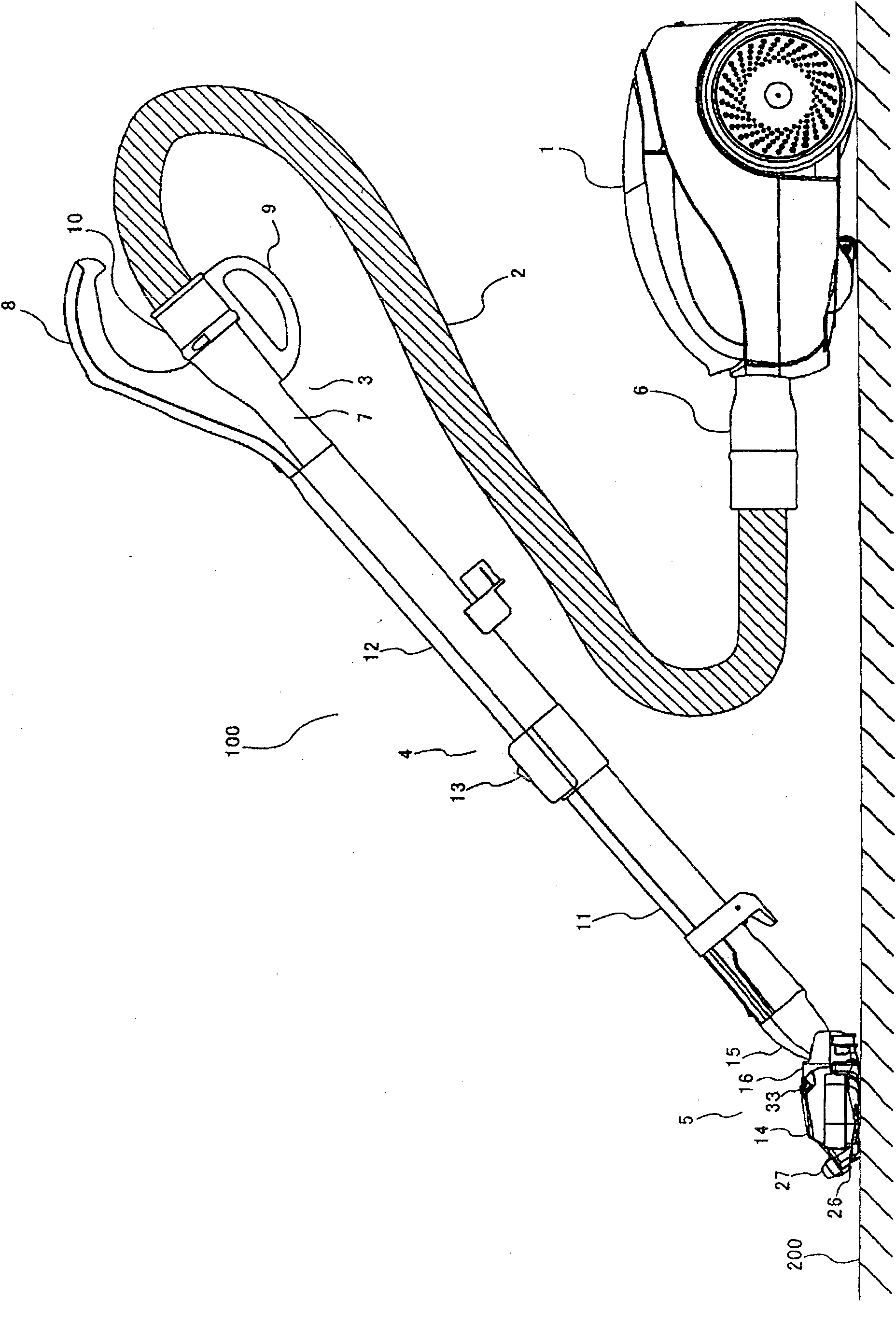
[0038] figure 1 It is a left side view of the electric vacuum cleaner which concerns on one Embodiment of this invention. In the following, for the convenience of explanation, figure 1 In the description, the left side is the front, the right side is the rear, the front side is the left, and the back side is the right. When explaining the components of the electric vacuum cleaner, the front and rear, left and right, and up and down are also distinguished according to their directions, and are explained at the same time. .

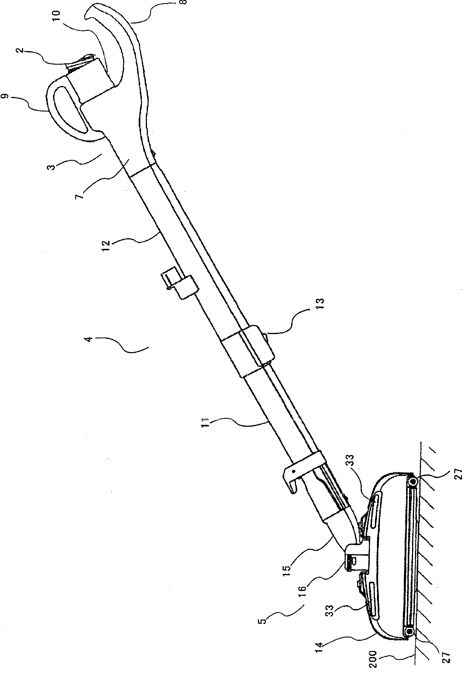
[0039] This electric vacuum cleaner 100 includes a canister-shaped vacuum cleaner main body 1 , a suction hose 2 , an operation part 3 , a suction pipe 4 , and a suction tool 5 . An electric blower (not shown) is built in the vacuum cleaner main body 1, and suction is generated by the electric blower.

[0040] The connection part 6 atta...


PUM


Abstract

The present invention provides an electric vacuum cleaner in which the suction part mainly used for the floor is low-cost, light-weight and easy to handle, and even if it is inserted into a narrow gap in a standing posture, the air inlet for driving the rotating brush is not blocked. clogged. In the housing (14) of the suction piece (5), there is a rotating brush (29) rotatably provided facing the main suction port (24) and the secondary suction port (25), and on the casing (14), the suction piece (5) An air inlet (33) is formed at a position where the airflow of the rotating brush (29) is rotationally driven to flow in at a position where it does not contact a standing surface (300) such as a wall surface in a standing position.

Description

technical field [0001] The present invention relates to an electric vacuum cleaner provided with a suction tool (floor suction tool) that mainly sucks dust from a floor surface as a surface to be cleaned. Background technique [0002] An electric vacuum cleaner generally has a vacuum cleaner main body with an electric blower, a suction hose with a rear end attached to the main body and an operation part at the front end, and a suction pipe with a rear end connected to the operation part of the suction hose and a suction tool at the front end. The user grips the handle provided on the operation part and moves the suction tool back and forth along the surface to be cleaned (floor surface) to perform cleaning. [0003] Conventionally, the suction tool has a so-called T-shaped shape connected to the suction pipe in order to efficiently suck dust on the surface to be cleaned when moving back and forth. That is, the suction tool has a casing having a predetermined width, thicknes...

Claims


Application Information

Patent Timeline
Patent Type & Authority Patents(China)
IPC IPC(8): A47L5/00A47L9/02A47L9/24
Inventor 秋山真一森田明宏鹿野裕隆土田英也福岛定男福本明广
Owner SANYO ELECTRIC CO LTD
Why Eureka
Try Eureka