Fast locking screw cap

A lock nut, fast technology, applied in the direction of locking fasteners, screws, nuts, etc., can solve the problems of slow speed, low efficiency, and user effort, and achieve the effect of easy use

Inactive Publication Date: 2009-08-12
XIAMEN OLT SCI & TECH ELECTRONICS DEVING
View PDF0 Cites 13 Cited by
  • Summary
  • Abstract
  • Description
  • Claims
  • Application Information

AI Technical Summary

Problems solved by technology

[0002] At present, the existing common nuts on the market can only be rotated up round by round and finally tightened. The efficiency is low and the speed is slow, and the user feels that it is very laborious.
room for improvement

Method used


Image

  • Fast locking screw cap
  • Fast locking screw cap
  • Fast locking screw cap

Examples


Embodiment 1

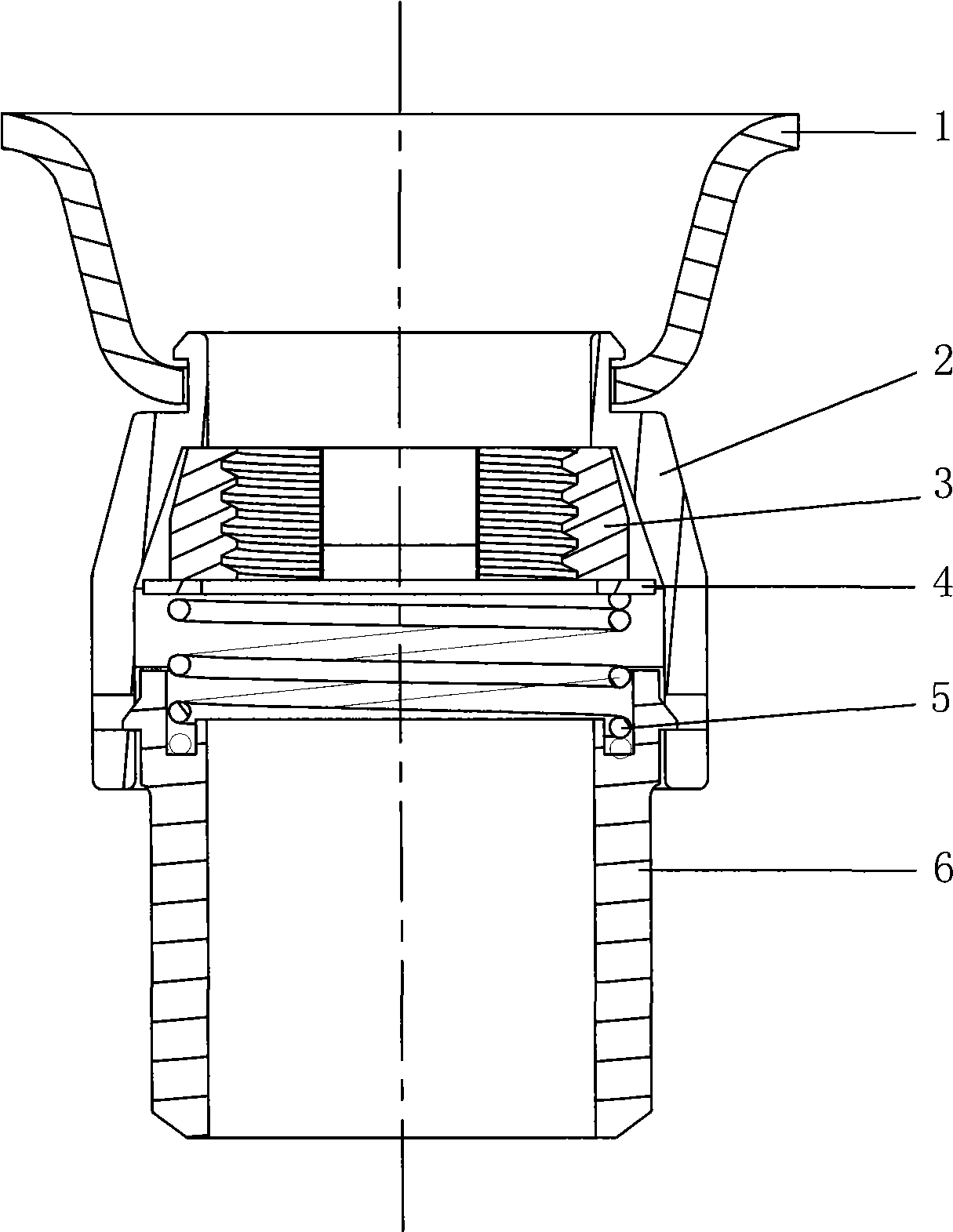
[0017] Such as figure 1 As shown, a quick locking nut has a hollow main body 2, a split thread 3 is provided on the cavity wall in the main body 2, and a spring 5 and a spring are fixed under the split thread 3. 5 hex bolts 6.

[0018] The axial section of the main body 2 is trumpet-shaped.

[0019] A flat washer 4 is provided between the split thread 3 and the spring 5 , and a washer 1 is provided on the upper end of the main body 2 .

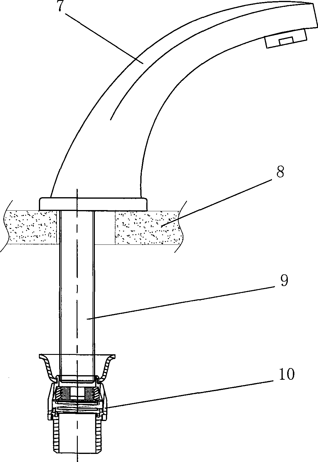
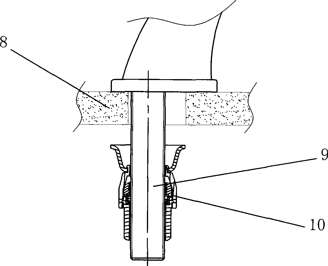
[0020] Figure 2 ~ Figure 4 It is the use state diagram of the present invention. Such as Figure 2 ~ Figure 4 As shown, when the faucet 7 is fixed under the basin 8, when the present invention slides upwards, the split threads 3 on both sides will move down and both sides, the spring 5 will shrink, and the threaded fixing rod 9 of the faucet 7 will pass smoothly. Split thread 3, after the split thread 3 is in place, the split thread 3 on both sides will move to the center under the action of the spring force, and play a role of tightenin...


PUM


Abstract

The invention discloses a fast locking nut, which is provided with a hollow main body, wherein the wall of a cavity in the main body is provided with divided threads, and a spring and a fixing piece for fixing the spring are arranged below the divided threads. The fast locking nut is a technical innovation for a water faucet fixing mode, and a water faucet can be tightened quickly by replacing a common nut with the fast locking nut; besides, the fast locking nut has the advantages of easy use and quickness.

Description

technical field [0001] The present invention relates to a mechanical fastener, in particular, the present invention is a quick locking nut. Background technique [0002] At present, the common nuts that are common in the existing market can only be rotated up round by round and finally tightened when used. The efficiency is low and the speed is slow, and the user feels that it is very laborious. There is room for improvement. Contents of the invention [0003] The object of the present invention is to provide a quick locking nut. The product of the present invention is a fast-tightening nut in the manner of straight upward pulling, which can play the role of quickly fixing the faucet under the basin. [0004] In order to achieve the above-mentioned purpose of the invention, the present invention adopts the following technical solutions: [0005] A quick locking nut has a hollow main body, a split thread is provided on the cavity wall in the main body, a spring and a fix...

Claims


Application Information

Patent Timeline
Patent Type & Authority Applications(China)
IPC IPC(8): F16B37/08F16B39/28
Inventor 吴端龙
Owner XIAMEN OLT SCI & TECH ELECTRONICS DEVING
Why Eureka
Try Eureka