Flash unit, camera, and camera flash system

A flash device and camera technology, applied in the camera body, camera, TV system parts and other directions, can solve the problems of battery consumption, confirm the irradiation area, increase power consumption, etc., and achieve the effect of reducing energy loss

Inactive Publication Date: 2009-08-12
OLYMPUS CORP
View PDF2 Cites 29 Cited by
  • Summary
  • Abstract
  • Description
  • Claims
  • Application Information

AI Technical Summary

Problems solved by technology

[0005] Simulation lights increase the power consumption for lighting and consume batteries
Since simulated lighting only temporar

Method used


Image

  • Flash unit, camera, and camera flash system
  • Flash unit, camera, and camera flash system
  • Flash unit, camera, and camera flash system

Examples


Embodiment Construction

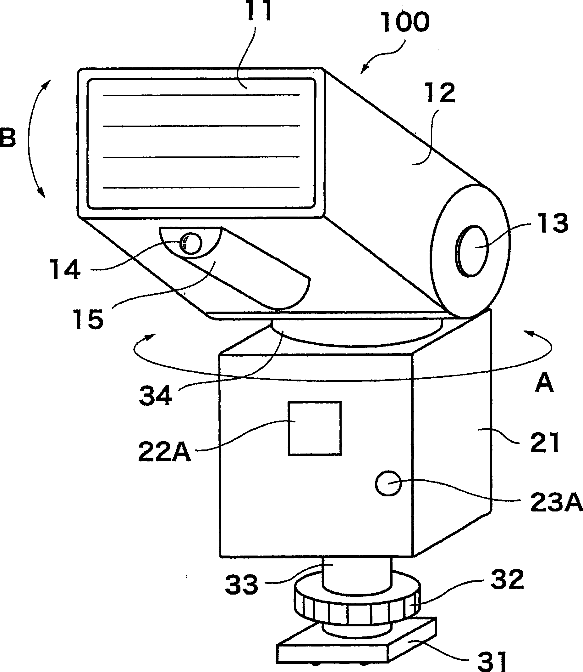
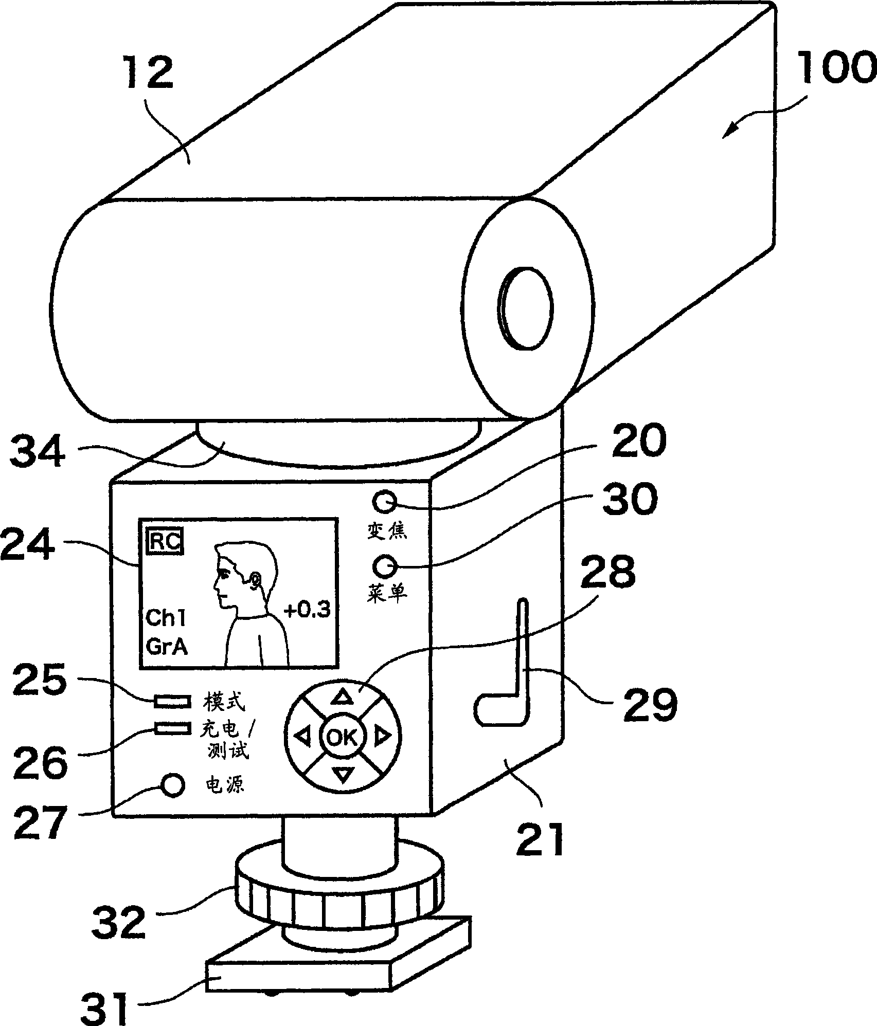
[0044] Hereinafter, a preferred first embodiment of a camera flash system composed of a camera 1 and a flash unit 100 to which the present invention is applied will be described with reference to the drawings. figure 1 It is a perspective view of the appearance of the strobe device 100 according to the first embodiment of the present invention viewed from the front, figure 2 It is an external perspective view of the strobe unit 100 viewed from the back.

[0045] A control circuit and the like for controlling the entire strobe device 100 are provided inside the strobe control unit main body 21 . An AF auxiliary light window 22A and a driven sensor window 23A are provided on the front side of the strobe control unit main body 21 . The AF auxiliary light window 22A is a window including a projection light lens for projecting auxiliary light for assisting automatic focusing of the camera by illuminating the subject when the subject is dark.

[0046] The driven sensor window 23A...


PUM


Abstract

The present invention provides a flashing light device which can correctly confirm the irradiation area of flashing light device configured separate from camera, the camera and a flashing light system of camera thereof. The flashing light system of camera is composed of the camera (1), the flashing light devices (100A, 100B) which are separated from the camera (1) and can be used as the auxiliary light sources of photography. The flashing light system of camera comprises the following components: a light emitting part (11) which irradiates flash light to the object being shot; a camera shooting unit (15) which can do camera shooting to the image comprising the object being shot in the irradiation area of light emitting part (11); a transceiver circuit (201) which transmits the shot image that is shot by the camera shooting unit (15) to the camera (1); a built-in flashing light device (64) which is used for outputting a control signal from the side of camera (1) to the flashing light devices (100A, 100B); a communication circuit (304) which receives the shot image of irradiation area from the flashing light devices (100A, 100B); and a back LCD (67) of camera (1), which displays the irradiation area.

Description

technical field [0001] The present invention relates to a flashlight device, a camera and a camera flashlight system, in particular, to a flashlight device that can be used as an auxiliary lighting device for a camera such as an imaging device, and can be used in a position fixedly installed on the camera or separated from the camera, A camera that can operate in conjunction with the flash unit, and a camera flash system composed of these. Background technique [0002] This application claims priority to prior Japanese Patent Application No. 2008-25952 filed on February 6, 2008. This application is expressly incorporated herein by reference. The scope of the invention is not limited by any requirement of the specific embodiments described in this invention. [0003] When shooting with the auxiliary light of the strobe device, it is necessary to take the photo in consideration of the irradiation area of ​​the strobe device. Especially when the flash unit is placed at a pos...

Claims


Application Information

Patent Timeline
IPC IPC(8): G03B15/05G03B7/16G03B15/02G03B15/03G03B17/18H04N5/225H04N5/238
CPCG03B15/05G03B2215/0528G03B2215/0532G03B2215/0535G03B2215/0557
Inventor 大久保光将
Owner OLYMPUS CORP
Why Eureka
Try Eureka