Optimal design method for reinforcement layout of thin-walled reinforced structures
A design method and optimization design technology, applied in computing, special data processing applications, instruments, etc., can solve problems such as inability to deal with parametric definition of reinforcement layout
- Summary
- Abstract
- Description
- Claims
- Application Information
AI Technical Summary
Problems solved by technology
Method used
Image
Examples
Embodiment 1
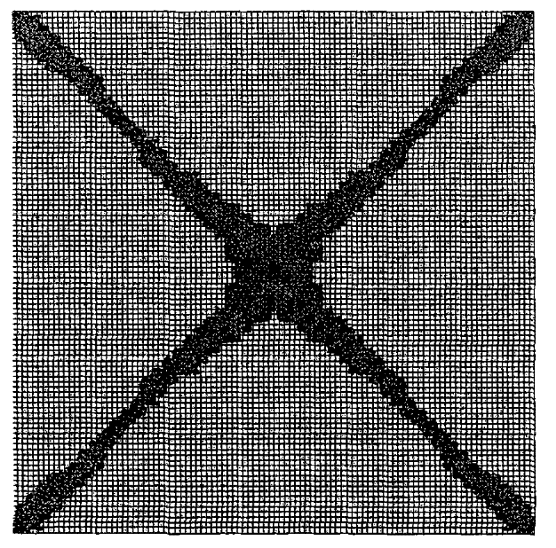
[0035] Example 1: The length and width of the substrate are both 0.1m, the thickness is 0.001m, and the height of the reinforcement is 0.004m. The four corners of the structure are supported at fixed points, and the center is subjected to the action of lateral concentrated load F=200N. Material elastic modulus E=2×10⁵Mpa, Poisson's ratio is 0.3. The design area of reinforcement is set as the space formed by the upper surface of the substrate along the normal direction of the substrate with a translation distance of 0.004m. The material consumption in the design area is 10%, and the initial value of the corresponding design variable is 0.1. The layout of reinforcement is designed to maximize the structural rigidity.
[0036] (1) Determine the optimal design area as the length, width and height above the surface of the substrate are 0.1×0.1×0.004m 3 The space area, the non-design area is the substrate 0.1×0.1×0.001m 3 The CAD model is established in the spatial area; the CAD...
Embodiment 2
[0055] Embodiment 2: The length and width of the substrate are both 0.1m, the thickness is 0.001m, and the height of the reinforcement is 0.004m. The four corners of the structure are supported at fixed points, and the center is subjected to the action of lateral concentrated load F=200N. Material elastic modulus E=2×10⁵Mpa, Poisson's ratio is 0.3. The design area of reinforcement is set as the space formed by the upper surface of the substrate along the normal direction of the substrate with a translation distance of 0.004m. The material consumption in the design area is 10%, and the initial value of the corresponding design variable is 0.1. The layout of reinforcement is designed to maximize the structural rigidity.
[0056] (1) Determine the optimal design area as the length, width and height above the surface of the substrate are 0.1×0.1×0.004m 3 The space area, the non-design area is the substrate 0.1×0.1×0.001m 3 The CAD model is established in the spatial area; the ...
Embodiment 3
[0075] Embodiment 3: The outer diameter of the spherical shell is R=0.07m, the thickness t=0.001m, the height of the internal reinforcement is h=0.004m, and the outer surface of the ball bears a certain non-uniform pressure. Elastic modulus E=2×10⁵Mpa, Poisson's ratio is 0.3, the reinforced design area is the spherical shell space between R1=0.065 and R1=0.069, and the material consumption is 20%. Find the spatial layout of the reinforcement to maximize the stiffness of the structure.
[0076] (1) Determine that the optimal design area is the spherical shell space between spherical radius R1=0.065m to R1=0.069m, and the non-design optimized area is the space area between spherical radius R=0.07m to R=0.069m, and establish CAD The model, that is, the spherical shell space with a radius of R=0.65~0.69m; the CAD model is divided into grids, and one-eighth of the model is modeled according to the symmetry; the non-design area is divided into regular hexahedral grids, and the desig...
PUM
 Abstract
Description
Claims
Application Information
 - R&D
- Intellectual Property
- Life Sciences
- Materials
- Tech Scout
- Unparalleled Data Quality
- Higher Quality Content
- 60% Fewer Hallucinations
Browse by: Latest US Patents, China's latest patents, Technical Efficacy Thesaurus, Application Domain, Technology Topic, Popular Technical Reports.
© 2025 PatSnap. All rights reserved.Legal|Privacy policy|Modern Slavery Act Transparency Statement|Sitemap|About US| Contact US: help@patsnap.com


