Motor unit

A technology for electric motors and mounting plates, which is applied in the direction of electromechanical devices, electric components, electrical components, etc., and can solve problems such as burrs or flashes on the shear surface and reduced driving accuracy

Inactive Publication Date: 2009-08-12
SANKYO SEIKI MFG CO LTD
View PDF1 Cites 0 Cited by
  • Summary
  • Abstract
  • Description
  • Claims
  • Application Information

AI Technical Summary

Problems solved by technology

[0004] However, since this mounting plate is formed by press working of a metal plate, burrs or flashes are generated on the sheared surface
Therefore, the presence of the burr or flash may cause the motor unit to be mounted obliquely on the motor drive device, or the driving accuracy of the driving object connected to the carriage (carriage) to decrease.

Method used


Image

  • Motor unit
  • Motor unit
  • Motor unit

Examples


no. 1 approach

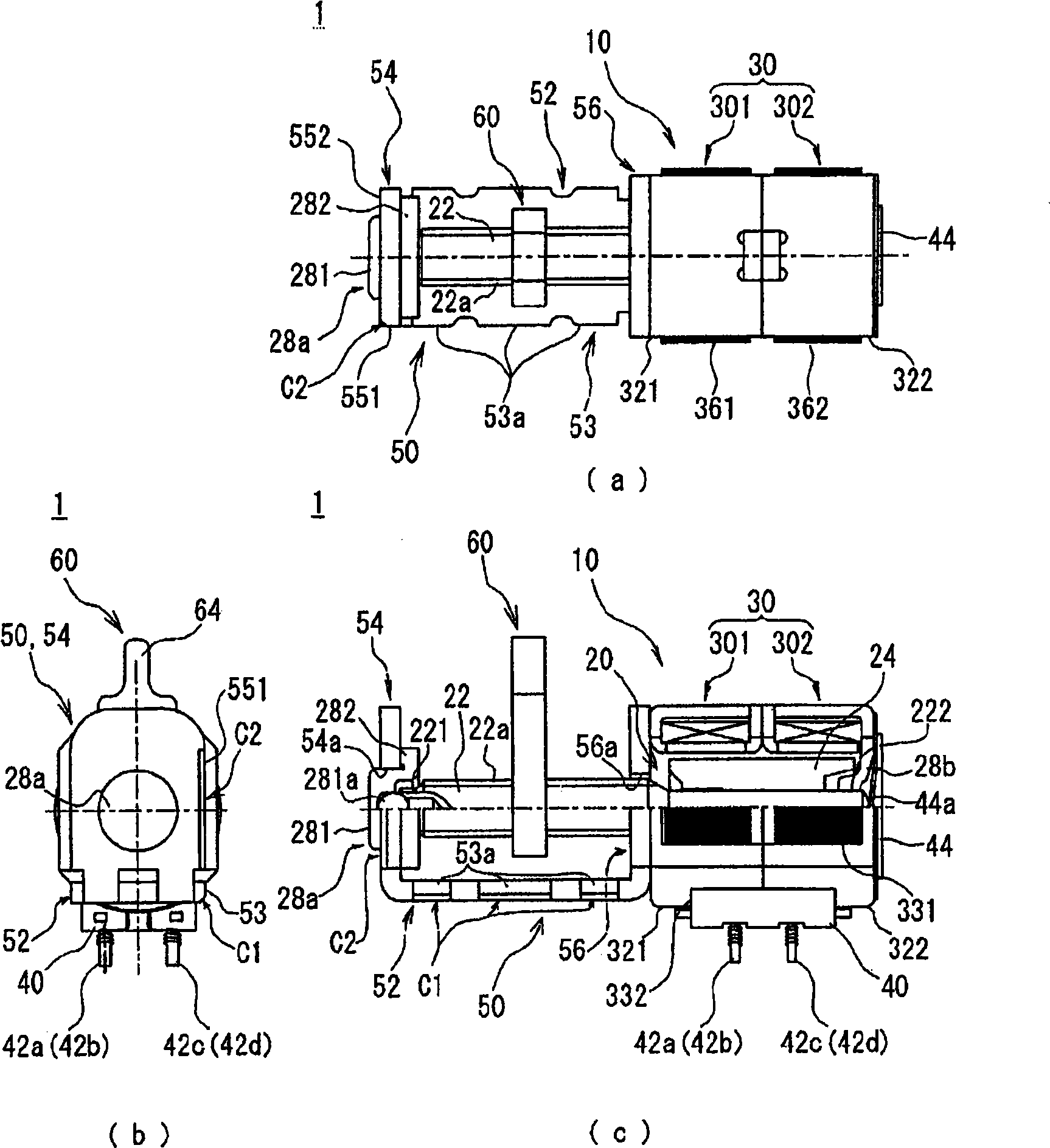
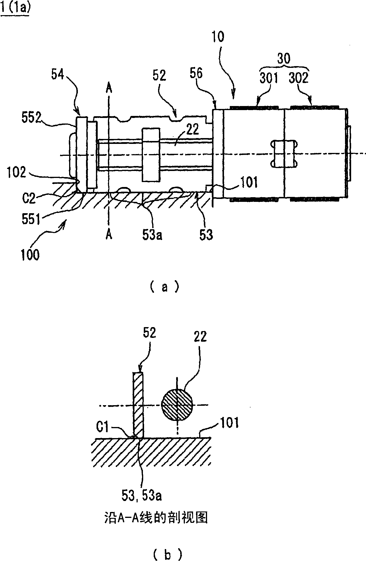
[0061] image 3 (a) is a figure which shows the state which mounted|worn the motor device 1a of 1st Embodiment to a motor drive facility. image 3 (b) is along image 3 (a) A cross-sectional view taken along line A-A. Such as image 3 As shown, the motor unit 1a is fixed in a state where one side surface 53 of the bottom plate portion 52 is in contact with the mounting surface 101 of the motor mounting portion 100 of the motor drive device. That is, the one side surface 53 of the bottom plate part 52 becomes a contact part which contacts a motor drive device.

[0062] Here, in the present embodiment, on the one side surface 53 of the bottom plate portion 52, as described above, the chamfering processing C1 is performed on the protruding portion 53a at three locations as the contact portion with the motor drive device. Burrs and burrs generated on the protruding portion 53a by press working (cutting work) are removed. Therefore, even if the motor unit 1a is laid on the mou...

no. 2 approach

[0069] exist image 3 In the first embodiment shown, the one side surface 53 of the bottom plate portion 52 and the one side surface 551 of the rotating shaft support portion 54 are used as abutting portions for abutting against the motor drive device, but they may also be used as Figure 4 The motor device 1b is constructed as shown in (a), except for the one side surface 53 of the bottom plate portion 52, the one side surface 57 of the stator support portion 56 ( Figure 4 The lower side surface in (a) also serves as an abutment portion that abuts against the motor drive device. When constituted in this way, like the first embodiment, the abutting portion of the motor unit 1b that abuts against the mounting surface 101 of the motor mounting portion 100 of the motor drive equipment is in an “L” shape, so that the motor unit 1b can be mounted in an installed state. become stable. In this case, in order to prevent the motor unit 1b from tilting,

[0070] It is necessary to p...

no. 3 approach

[0072] In the first embodiment and the second embodiment, the one side surface 53 of the bottom plate portion 52 and the one side surface 551 of the rotating shaft support portion 54, or the one side surface 53 of the bottom plate portion 52 and the one side surface 57 of the stator support portion are used as the motor device. The abutment part of the abutment, the abutment part is "L" shaped, but it can also be as Figure 4 The motor unit 1c is configured as shown in (b), and one side surface 53, 551, 57 of the bottom plate portion 52, the rotating shaft support portion 54, and the stator support portion 56 is used as an abutting portion for the motor drive device. With this structure, the abutting portion has a U-shape with respect to the mounting surface 101 of the motor mounting portion 100 of the motor drive device, so that the mounting state of the motor unit 1c can be made more stable. In addition, it is necessary to similarly perform cutting or grinding on the respect...


PUM


Abstract

A motor device is disclosed, which can shorten installation space of the motor device in a height direction on condition of maintaining higher control precision of a driven object. The motor device (1) comprises: a motor body (10) having a stator part (30) and a rotary shaft (22) protruding from the stator part (30), and a mounting plate (50) which is used for mounting the motor body (10) on a motor driving apparatus that receives rotary power from the motor body (10), and which is formed by cutting off a metal plate and comprises: a tabular bottom plate part (52), a stator support part (56) which is vertically formed on the bottom plate part (52) and is fixedly connected to the stator part (30), and a rotary shaft support part (54) which is arranged opposite to the stator support part (56); and on one side of the bottom plate part (52), the stator support part (56) and the rotary shaft support part (54), chamfering processing is implemented on an abutting part that abuts against the motor driving apparatus.

Description

technical field [0001] The present invention relates to a motor device, and more particularly, to a motor device including a mounting plate for fixing a motor body on a motor drive device using a motor as a drive source. Background technique [0002] Conventionally, there is known a motor device mounted on a motor-driven device using a motor as a drive source (for example, an optical head device including an optical lens, etc.). Such a motor device includes a metal mounting plate for fixing a motor body to a motor drive device (for example, refer to Patent Document 1). As in Patent Document 1 figure 2 As shown in (b), such a motor device is generally fixed by bringing the bottom plate portion of the mounting plate into contact with a housing or the like of the motor drive device. [0003] Patent Document 1: Japanese Patent Laid-Open No. 2000-139057 [0004] However, since the mounting plate is formed by press working of a metal plate, burrs or flashes are generated on the...

Claims


Application Information

Patent Timeline
Patent Type & Authority Applications(China)
IPC IPC(8): H02K37/24
CPCH02K7/06H02K5/04H02K37/14H02K5/00H02K7/00H02K37/02
Inventor 園原宏幸
Owner SANKYO SEIKI MFG CO LTD
Why Eureka
Try Eureka