Cooking Oil Removal Panel Construct

A structure and panel technology, applied in the direction of oil fume removal, application, household stoves, etc., can solve the problems of difficult panel separation, inconvenient handling and cleaning, etc., and achieve the effects of improved degreasing effect, easy handling, and easy installation

Active Publication Date: 2015-10-07
TOYO ALUMINUM EKCO PRODUCTS KK
View PDF8 Cites 0 Cited by
  • Summary
  • Abstract
  • Description
  • Claims
  • Application Information

AI Technical Summary

Problems solved by technology

[0006] In the above-mentioned conventional panel connection structure, since the curling is directly engaged, it is difficult to separate the panels, and it is inconvenient to handle and clean.

Method used


Image

  • Cooking Oil Removal Panel Construct
  • Cooking Oil Removal Panel Construct
  • Cooking Oil Removal Panel Construct

Examples


Embodiment Construction

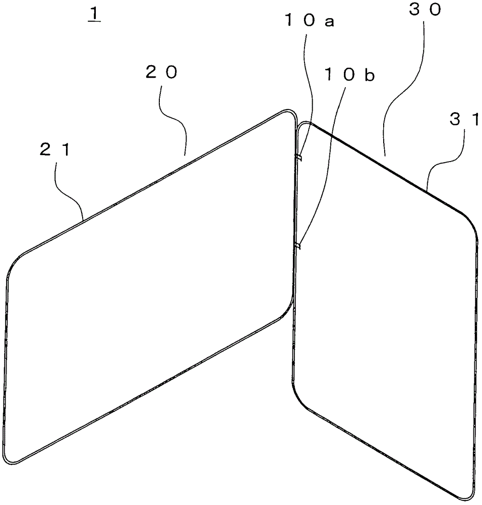
[0044] figure 1 It is a perspective view of the cooking oil removal panel structure of 1st Embodiment of this invention.

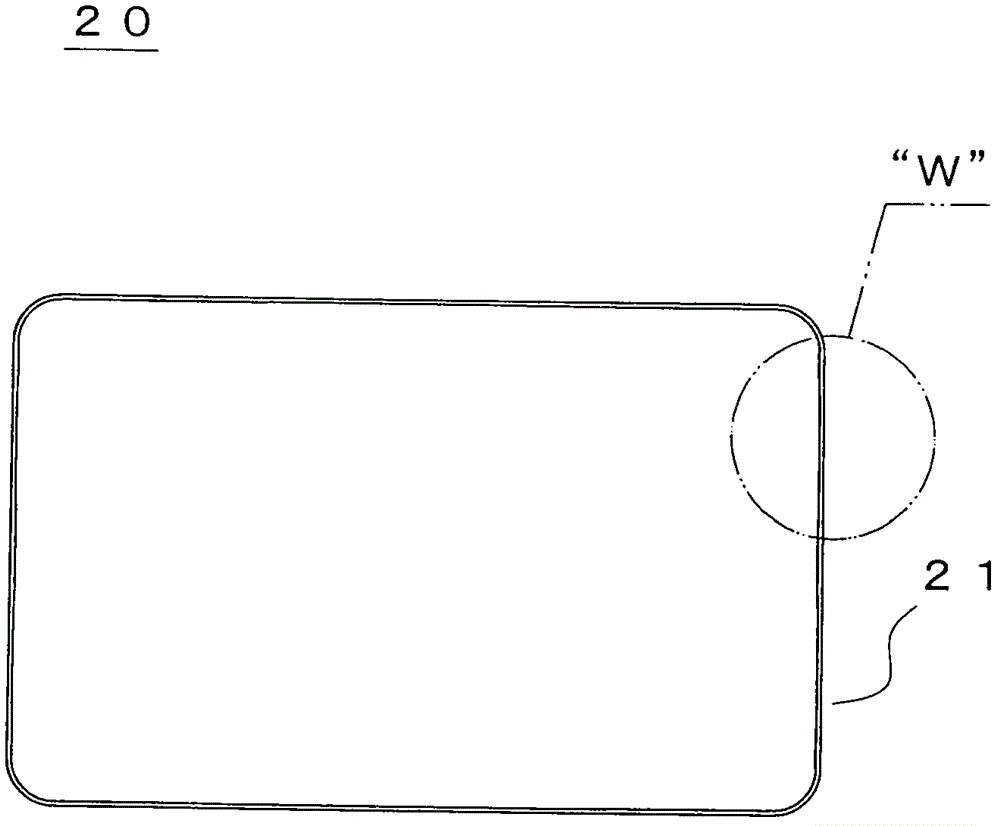
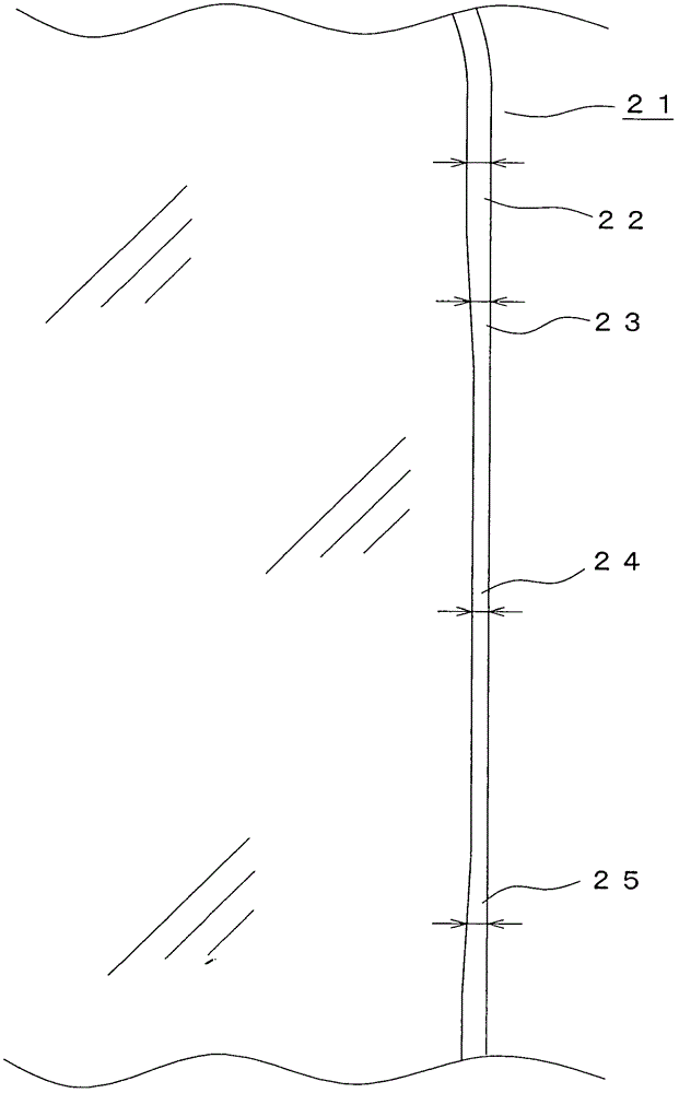
[0045] Referring to the drawings, the first panel 20 and the second panel 30 are connected by the panel connectors 10a and 10b to form the cooking oil removal panel structure 1 . The first panel 20 and the second panel 30 are press-formed iron plates, each having a rectangular sheet shape with rounded corners, and a first bead 21 having a winding diameter described later is formed on the entire circumference of the first panel 20. , a second bead 31 with a winding diameter of 3 mm is formed on the entire circumference of the second panel 30 . The first panel 20 is set to have a width of 600 mm and a width of 380 mm, and the second panel 30 is set to have a width of 380 mm and a width of 520 mm. In addition, the lower end of the first panel 20 is set at a position higher than the lower end of the second panel 30 by 175 mm.

[0046]In addition, the facin...


PUM


Abstract

The invention relates to a panel strcuture (1) for removing cooking oil. A first panel (20) with a curly edge and a second panel (30) with a curly edgeare arranged on the circumference of the panel structure, wherein the first panel and the second panel are connected in an orthogonal manner with almost no gaps via panel connecting members (10a) and (10b). When the panel is used, the first panel (20) is disposed on the upper surface of the top plate (62) of a cooking utensil (61) and the second panel (30) is disposed on the upper surface of a cooking utensil bench (63), such that the cooking utensil (61) can be surrounded for effective assembly, and the second panel (30) is not liable to fall from the cooking utensil (61) by accident. In addition, the first panel (20) and the second panel (30) can move correspondingly on each surface by means of the panel connecting members (10a) and (10b). Therefore, the layout and the arrangement become simple based on types of the cooking utensil (61).

Description

technical field [0001] The present invention relates to a cooking oil removal panel structure, and more particularly relates to a cooking oil removal panel structure composed of two connected panels having curls. Background technique [0002] Figure 16 It is a perspective view showing the state of use of a conventional cooking oil removal panel disclosed in Japanese Patent Application Laid-Open No. 2002-106526, Figure 17 yes Figure 16 An enlarged view of the "Z" portion of the Figure 18 is from Figure 17 A perspective view of a change in a state in which the front panel is lifted upwards. [0003] Referring to these drawings, the cooking oil removal panel 80 is formed by bending a thin iron plate, aluminum plate, etc., and consists of a rectangular flat front panel 81 and a rectangular flat right side connected to the right side of the front panel 81. The side panel 85 is constituted by a rectangular flat left side panel 89 connected to the left side of the front pan...

Claims


Application Information

Patent Timeline
Patent Type & Authority Patents(China)
IPC IPC(8): F24C15/12
Inventor 井上太郎山岸拓人
Owner TOYO ALUMINUM EKCO PRODUCTS KK
Why Eureka
Try Eureka