Rheometer

A technology of rheometer and magnetorheological fluid, which is applied in the field of rheometer and can solve problems such as limiting the measurement range of rheometer

Active Publication Date: 2009-08-12
安东帕有限责任公司
View PDF9 Cites 19 Cited by
  • Summary
  • Abstract
  • Description
  • Claims
  • Application Information

AI Technical Summary

Problems solved by technology

However, in rheometers known from the prior art, the permissible normal force is limited upwards due to the arrangement of bearings, for example air bearings, thus limiting the measuring range of the rheometer

Method used


Image

  • Rheometer

Examples


Embodiment Construction

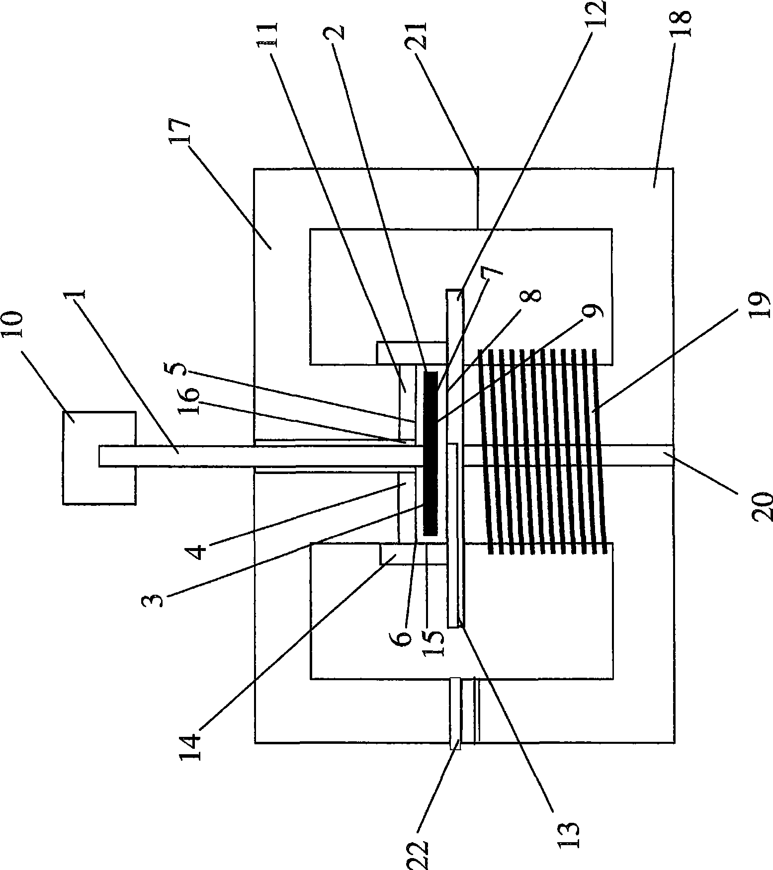
[0040] The rheometer comprises a rotating shaft 1 made of non-magnetizable material, eg austenitic stainless steel material number 1.4571. The rotary shaft 1 is connected to a motor (not shown) that drives the shaft 1 . The shaft is preferably supported using air bearings (not shown). A rotor disk 2 made of a magnetizable material (for example steel material number 1.0037) is attached to the end of the shaft 1 . exist figure 1 Between the upper side (first side 3 ) of the rotor disk 2 and the first shear plane 4 , a first measurement gap 5 containing a substance 6 to be investigated (for example a magnetorheological fluid) is located. Between the underside (second side 7 ) of the rotor disk 2 and the second shear plane 8 there is formed a second measuring gap 9 which also accommodates the substance 6 to be investigated.

[0041] The rheometer also includes a measuring device 10 , which measures the rotational speed and the torque of the motor and thus also indirectly detec...


PUM

PropertyMeasurementUnit
radiusaaaaaaaaaa
radiusaaaaaaaaaa
radiusaaaaaaaaaa

Abstract

The invention relates to a rheometer, comprising a rotatable shaft (1), to which a rotor plate (2) is fixed, and a measuring device (10), for measuring torques exerted on the rotor plate (2) by a substance under investigation during a rotation of the shaft (1), wherein a first measuring gap (5), for accommodating the substance (6) under investigation, is formed between a first side (3) of the rotor plate (2) and a first shear surface (4) and a second measuring gap (9), for accommodating the substance (6) under investigation, is formed between a second side (7) of the rotor plate (2) away fromthe first and a second shear surface (8). The rheometer contains a magnet for generating a magnetic field in the first and second measuring gaps (5, 9).

Description

technical field [0001] The invention relates to a rheometer with a rotor disk fixed on a rotating shaft and to a method for determining the rheological properties of a substance to be investigated with the rheometer. Background technique [0002] Rheology is the science of flow processes—the continuous deformation of materials under the action of external forces. Flow deformation (viscous deformation) occurs at a finite rate. In real materials, viscous properties are superimposed by plastic and elastic properties. Rheometry was measured using various rheometers according to the prior art. There are differences between rotational rheometers, capillary rheometers, extensional rheometers and compression rheometers. [0003] In the laboratory, rotational rheometers are most widely used. Usually three different measuring systems with different geometries are used here. These different measuring systems include cone / disk-measuring systems, disc / disk-measuring systems and cyli...

Claims


Application Information

Patent Timeline
Patent Type & Authority Applications(China)
IPC IPC(8): G01N11/14
CPCG01N2011/0026G01N11/14G01N27/00
Inventor M·劳恩J·普菲斯特R·洛赫特曼G·奥特C·加布里埃尔
Owner 安东帕有限责任公司
Why Eureka
Try Eureka