Fluidics devices for individualized coagulation measurements and associated systems and methods

a technology of coagulation measurement and fluidics device, which is applied in the direction of fluid controllers, laboratory glassware, instruments, etc., can solve the problems of inability to control the hemorrhaging of the tic, the inability of the response team to quickly detect the uncontrolled hemorrhaging, and the inability to achieve hemostasis, so as to achieve and maintain hemostasis, the effect of reducing the strength of the clot and impairing the stabil

Inactive Publication Date: 2016-12-15
UNIV OF WASHINGTON
View PDF4 Cites 14 Cited by
  • Summary
  • Abstract
  • Description
  • Claims
  • Application Information

AI Technical Summary

Benefits of technology

[0005]At least three clot parameters—clot strength, clot onset, and clot lysis—are recognized as important for achieving and maintaining hemostasis. As used herein, “clot strength” refers to the peak clot contractile force, “clot onset” refers to the time it takes for a clot to form, and “clot lysis” refers to the decrease in clot strength after peak contraction. TIC impacts one or more of these clot parameters which ultimately impairs stable clot formation. For example, TIC can reduce clot strength, as TIC often leads to hypoperfusion (i.e., insufficient blood supply to vital organs), and hypoperfusion leads to reduced thrombin generation and thus reduced fibrin F formation around the platelet plug. TIC can also enhance or accelerate clot lysis by increasing the availability of tissue plasminogen activator (tPA), a protein that converts plasminogen to plasmin (i.e., the enzyme responsible for clot breakdown by breaking down the fibrin F mesh). Hypoperfusion also accelerates clot lysis due to the resulting build-up of lactic acid and reduction in pH levels.
[0028]FIG. 2B is an enlarged view of a portion of the second chamber 222b of FIG. 2A, and FIG. 2C is an enlarged view of a portion of FIG. 2B. Referring to FIGS. 2A-2C together, each chamber 222 can include an array (identified individually as first through fifth arrays 221a-e; referred to collectively as arrays 221) of sensing units 211. The sensing units 211 can be arranged within the respective array 221a-e such that individual sensing units 211 in adjacent rows are offset from one another (as shown in FIG. 2B). In other words, the sensing units 211 can be arranged such that no sensing unit 211 is directly aligned with another sensing unit 211 in the immediately adjacent row. This configuration is expected to reduce the downstream effects of flow disturbances caused by upstream sensing units 211.
[0029]As best shown in FIG. 2C, each sensing unit 211 can include a generally rigid structure, such as a microblock 212 and a generally flexible structure, such as a micropost 214. The micropost 214 can be positioned downstream of the microblock 212 and in general alignment with a center line of the microblock 212. In certain embodiments, the micropost 214 can be positioned within about 8 μm (measured from edge to edge) of the microblock 212 so that biological sample components (e.g., cells) that aggregate on the microblock 212 are able to bridge the gap between the microblock 212 and the micropost 214. In other embodiments, the micropost 214 and the microblock 212 may be spaced apart by a greater or smaller distance depending upon the size of the biological components being analyzed.
[0032]Referring to FIGS. 3 and 4A-4B together, as the biological sample flows over the sensing units 211, each microblock 212 acts as a flow obstruction and causes an eddy. The eddy produces a high shear rate at the outermost top edges of the microblock 212 which activates the platelets P within the passing blood sample. The activated platelets P then bind to the microblock 212 (and to one another) as the platelets begin to aggregate. As shown in FIGS. 4B-4D, as an aggregation AP of platelets P grows larger in size, some of the platelets P breach the interstitial space between the microblock 212 and the micropost 214. For example, dual strands of collecting platelets P tend to form at the downstream corners of the microblock 212. As the platelet strands accumulate in length, the passing fluid pushes the strands inwardly and into contact with the micropost 214, thereby forming a mechanical bridge between the microblock 212 and the micropost 214. As more biological sample flows through the chamber 222, more platelets P accumulate and fill in the space between the microblock 212 and the micropost 214. In some embodiments, the microblock 212 and / or micropost 214 can be at least partially coated with at least one binding element (e.g., proteins, glycans, polyglycans, glycoproteins, collagen, etc) to improve and / or facilitate attachment of the platelets P to the microblock 212 and / or micropost 214.
[0038]In a particular embodiment, the measuring element 203 can include an optical detection component that is configured to optically measure micropost deflection, such as a phase contrast microscope, a fluorescence microscope, a confocal microscope, or a photodiode. For example, FIG. 7 is a schematic side view of one embodiment of an optical measuring element 205 configured in accordance with the present technology. The fluidics device 204 can be positioned between a first portion 205a and a second portion 205b of the optical measuring element205. In a particular embodiment, the fluidics device 204 can be inserted into a slot 296 in the optical measuring element 205 (and / or the analyzer 202 (e.g., via the port 224 (FIG. 2A)). The first portion 205a can be adjacent a first side of the slot 296, and the second portion 205b can be adjacent a second side of the slot 296 opposite the first side. The surfaces of the first and / or second side of the slot 296 can include first and second windows 298, 292, respectively, that are transparent or generally transparent. In other embodiments, the fluidics device 204 and / or the slot 296 can be positioned adjacent the first portion 205a and the second portion 205b without being between the first portion 205a and the second portion 205b. However, it is believed that a linear arrangement of the first portion 205a, the fluidics device 205b, and the second portion 205a can be advantageous as such an arrangement requires less space within the analyzer 202 (FIG. 2A).
[0046]It can be appreciated that coordination of the delivery of the biological sample to the arrays, the time measurements, and the force measurements can be advantageous to accurate deflection and / or force data. As such, the fluidics device 204 (FIG. 2A) can include a barrier (not shown) that prevents the biological sample from flowing from the inlet 210 (or beginning portion of the inlet channel 216) to the plurality of arrays 221a-e. Accordingly, a clinician can first deliver the biological sample to the inlet 210, and then position the fluidics device 204 in the analyzer 202. The analyzer 202 can include a trigger (e.g., a sharp edge to cut the barrier, a chemical to dissolve the barrier, etc.) that fluidly connects the backed up biological sample with the arrays 221a-e. In other embodiments, the biological sample can be delivered to the fluidics device 204 already positioned at least partially within the analyzer 202. Delivery of the biological sample can trigger the timer to start and / or the clinician can start the timer immediately before delivering the biological sample to the device 204. In yet other embodiments, the timer can be continuously running.II. SELECTED EMBODIMENTS OF CLOT ANALYZING SYSTEMS, DEVICES AND METHODS FOR INDIVIDUALIZED MEASUREMENTS, DIAGNOSIS AND / OR TREATMENT

Problems solved by technology

Uncontrolled hemorrhaging during TIC may not be readily apparent to the response team, as often times the hemorrhaging occurs internally.
TIC occurs almost immediately after injury and is associated with a several fold increased incidence of multi-organ failure, intensive care utilization, and death.
TIC impacts one or more of these clot parameters which ultimately impairs stable clot formation.
For example, TIC can reduce clot strength, as TIC often leads to hypoperfusion (i.e., insufficient blood supply to vital organs), and hypoperfusion leads to reduced thrombin generation and thus reduced fibrin F formation around the platelet plug.
Although the measurements taken from TEG devices have been shown to be more sensitive and accurate indicators of clotting than those taken using other conventional tests (e.g., prothrombin time (PT), activated partial thromboplastin time (aPTT), international normalized ratio (INR), etc.), TEG devices are large (generally used as bench-top devices), expensive, and sensitive to movement.
Accordingly, TEG devices are not appropriate as true point-of-care devices capable of determining a clot parameter value and / or making a measurement at the patient's bedside where early detection of TIC is needed.
Moreover, TEG devices require 20-30 minutes to produce a reading, which means that a first reading from either device is typically not available to the treatment clinician(s) until well past the golden hour.
Given that approximately one third of patients arriving to the ER die within 15 minutes of arrival, waiting 20-30 minutes for a reading from a TEG device is unsatisfactory for diagnosing TIC.
Such potentially inaccurate or uninformed diagnoses of TIC is concerning, as there are high risks associated with transfusion of blood components, including multiple organ failure, acute respiratory distress syndrome (ARDS), increased infection, and increased mortality.

Method used


Image

  • Fluidics devices for individualized coagulation measurements and associated systems and methods
  • Fluidics devices for individualized coagulation measurements and associated systems and methods
  • Fluidics devices for individualized coagulation measurements and associated systems and methods

Examples


Embodiment Construction

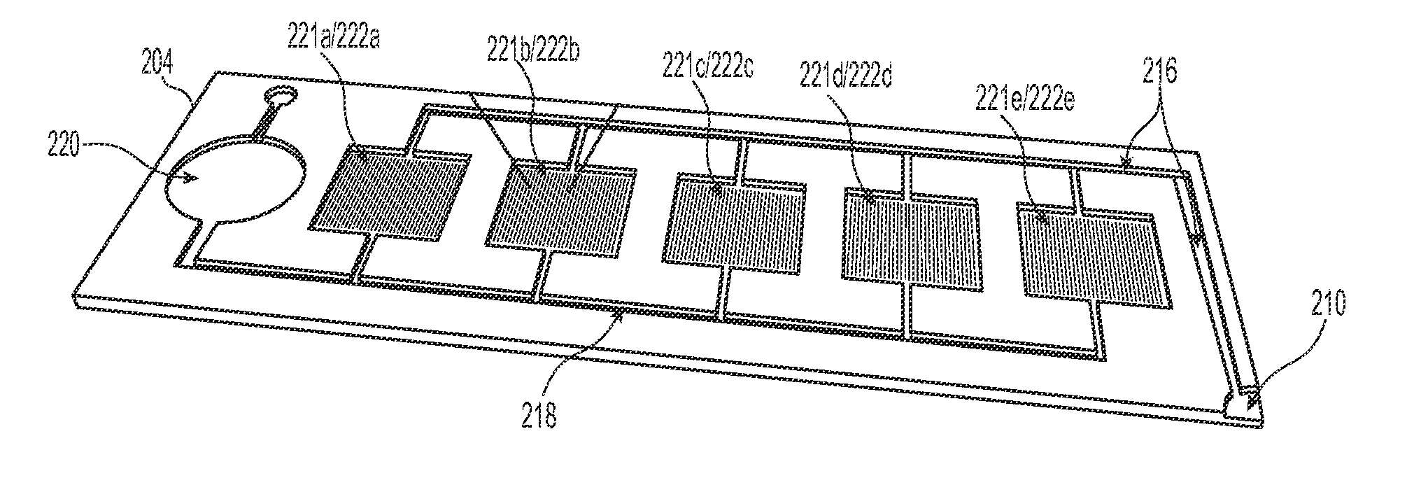
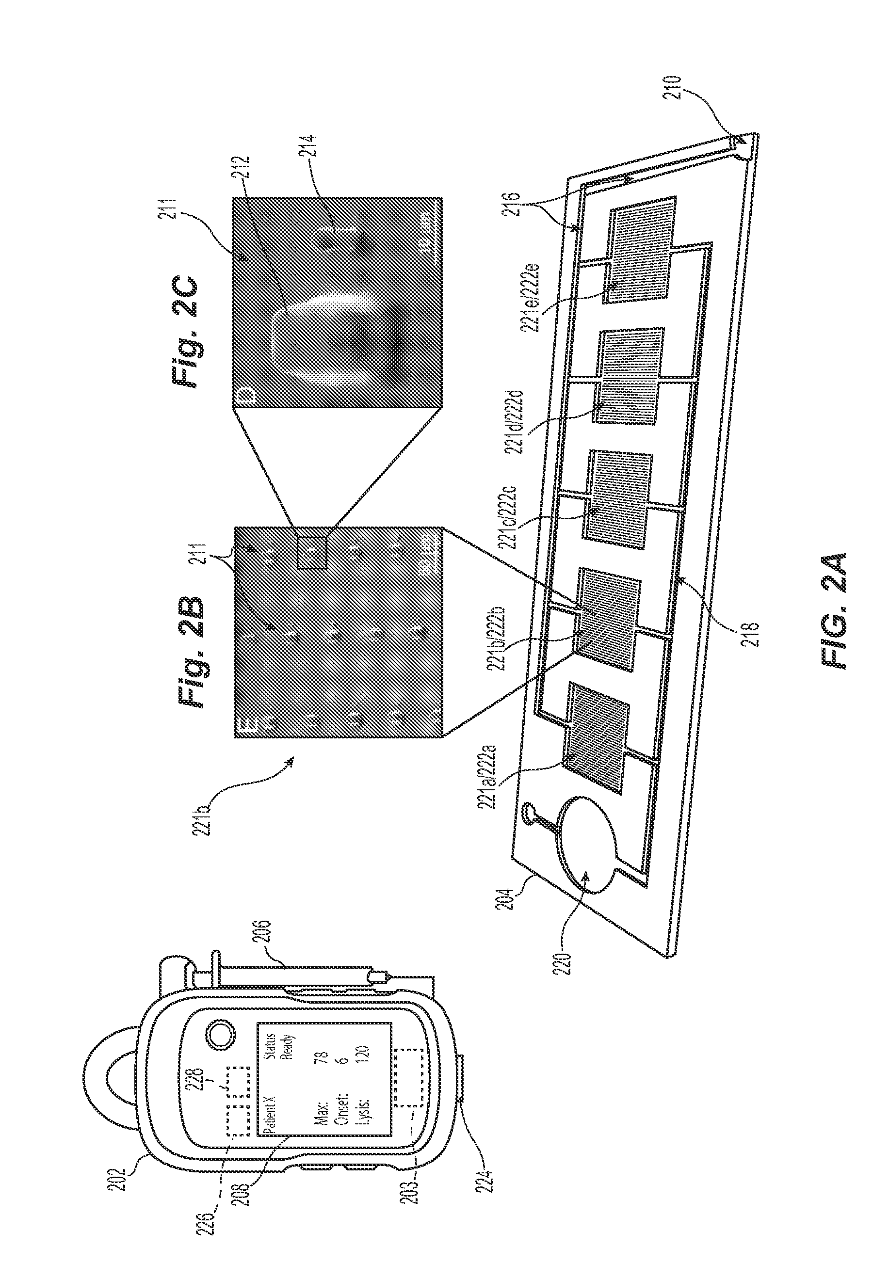
[0023]The present technology describes various embodiments of devices, systems, and methods for measuring one or more clot parameters. In one embodiment, for example, the system includes a plurality of arrays of microstructures, wherein each microstructure includes a generally rigid structure and a generally flexible structure. A first array can be configured to be in fluid connection with a first clotting agent, a second array can be configured to be in fluid connection with a second clotting agent different than the first clotting agent, and a third array is not in fluid connection with the first clotting agent or the second clotting agent. The system can further include a plurality of fluid channels configured to receive a biological sample flowing therethrough. At least a portion of the fluid channels can be individually sized to accept one of the arrays. In some embodiments, the system can include a measuring element that is configured to detect a degree of deflection of one or...


PUM

PropertyMeasurementUnit
heightaaaaaaaaaa
heightaaaaaaaaaa
heightaaaaaaaaaa

Abstract

The present technology relates generally to fluidics devices for measuring platelet coagulation and associated systems and methods. In some embodiments, a fluidics device includes an array of microstructures including pairs of generally rigid blocks and generally flexible posts. The fluidics device further includes at least one fluid channel configured to accept the array. The fluidics device can further include a measuring element configured to measure a degree of deflection of one or more of the flexible posts in the array. In some embodiments, the fluidics device comprises a handheld device and usable for point of care testing of platelet forces and coagulation.

Description

CROSS-REFERENCE TO RELATED APPLICATIONS[0001]This application claims the benefit of U.S. Provisional Application No. 61 / 839,723, filed Jun. 26, 2013, titled “Device and Method for Multiplexed Patient Specific Platelet Thrombosis and Fibrinolysis Testing with Internal Controls,” which is incorporated herein by reference in its entirety.TECHNICAL FIELD[0002]The present technology relates generally to fluidics devices for making individualized coagulation measurements, and associated systems and methods.BACKGROUND AND SUMMARY[0003]Trauma accounts for one in ten, or approximately five million, deaths annually worldwide and consumes over $135 billion in U.S. annual healthcare expenditure. The majority of trauma deaths occur within the first hour after injury (the “golden hour”) from uncontrolled hemorrhaging. Trauma-induced coagulopathy (TIC), or impaired clot formation, contributes to this uncontrolled hemorrhaging and is present in about 25% of trauma patients. Uncontrolled hemorrhagin...

Claims


Application Information

Patent Timeline
Patent Type & Authority Applications(United States)
IPC IPC(8): G01N33/86B01L3/00
CPCG01N33/86B01L3/502715B01L3/502738B01L2300/123B01L2300/025B01L2300/0819B01L2300/0832G01N2800/224B01L2300/0627B01L3/502746B01L3/502761B01L2300/027B01L2300/0663B01L2300/0887B01L2400/0487B01L2400/086
Inventor SNIADECKI, NATHAN J.WHITE, NATHAN J.KARCHIN, ARITING, LUCAS H.
Owner UNIV OF WASHINGTON
Why Eureka
Try Eureka