
Masking to prevent overexposure and light spillage in microarray scanning

A microarray and mask technology, applied in the field of scanning systems, can solve the problems of undesired exposure, leakage, light leakage, etc.

Inactive Publication Date: 2009-08-12
BIO RAD LAB INC
View PDF6 Cites 2 Cited by
  • Summary
  • Abstract
  • Description
  • Claims
  • Application Information

AI Technical Summary

Problems solved by technology

Light leaks also occur when a single process only covers a portion of a row, leaking into the portion of the row that was not scanned
In all cases, leakage can cause unwanted overexposure or background noise in the scanned signal, or both

Method used


Image

  • Masking to prevent overexposure and light spillage in microarray scanning
  • Masking to prevent overexposure and light spillage in microarray scanning
  • Masking to prevent overexposure and light spillage in microarray scanning

Examples


Embodiment Construction

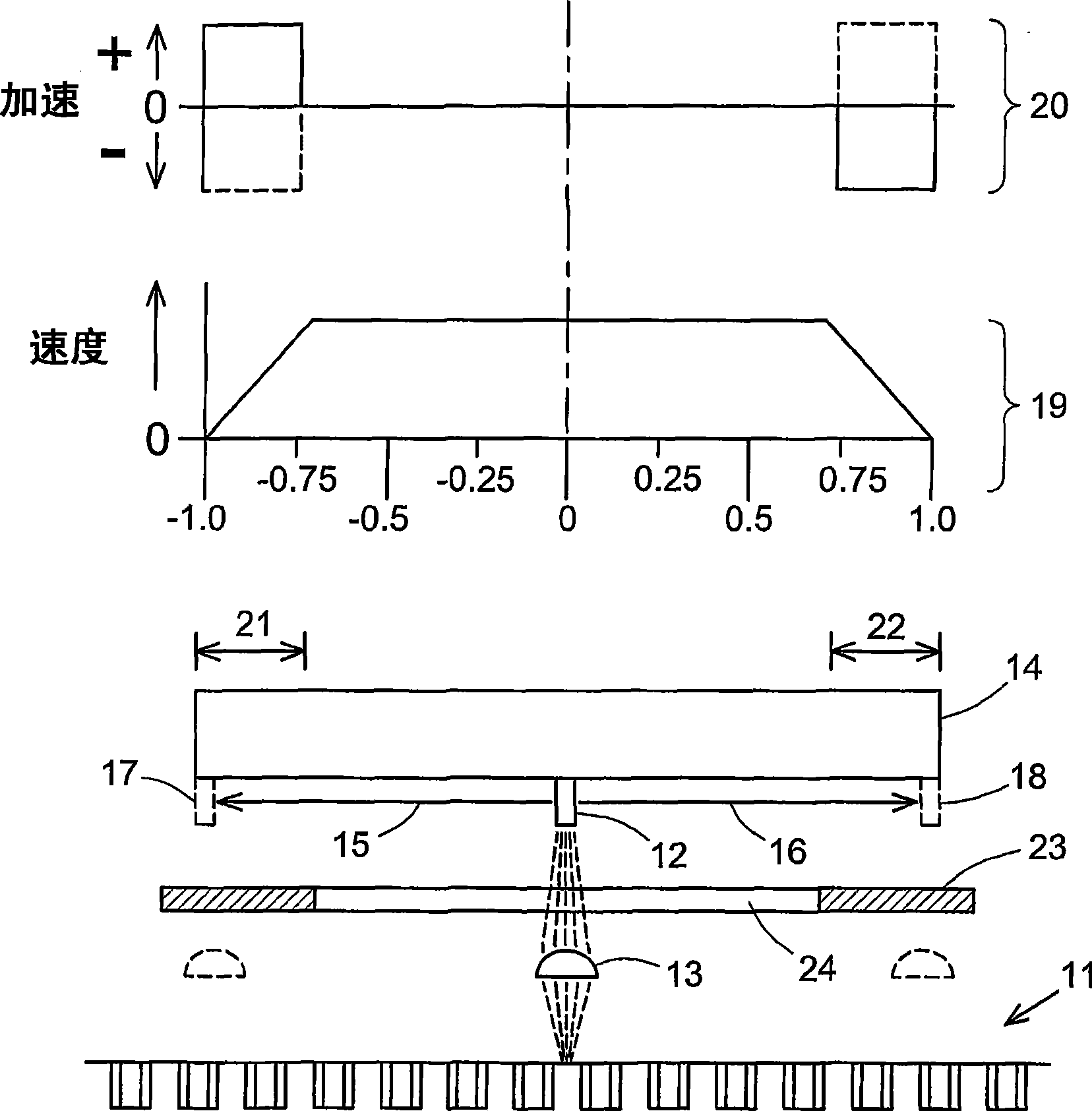
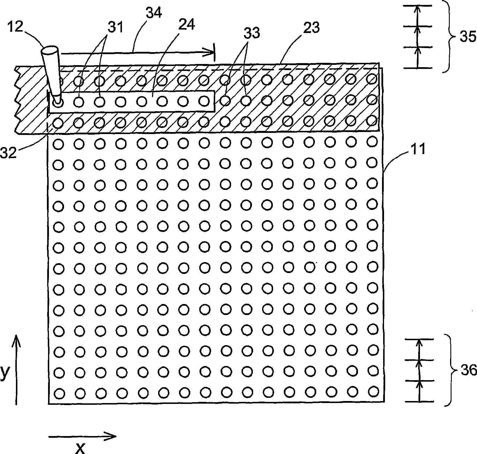
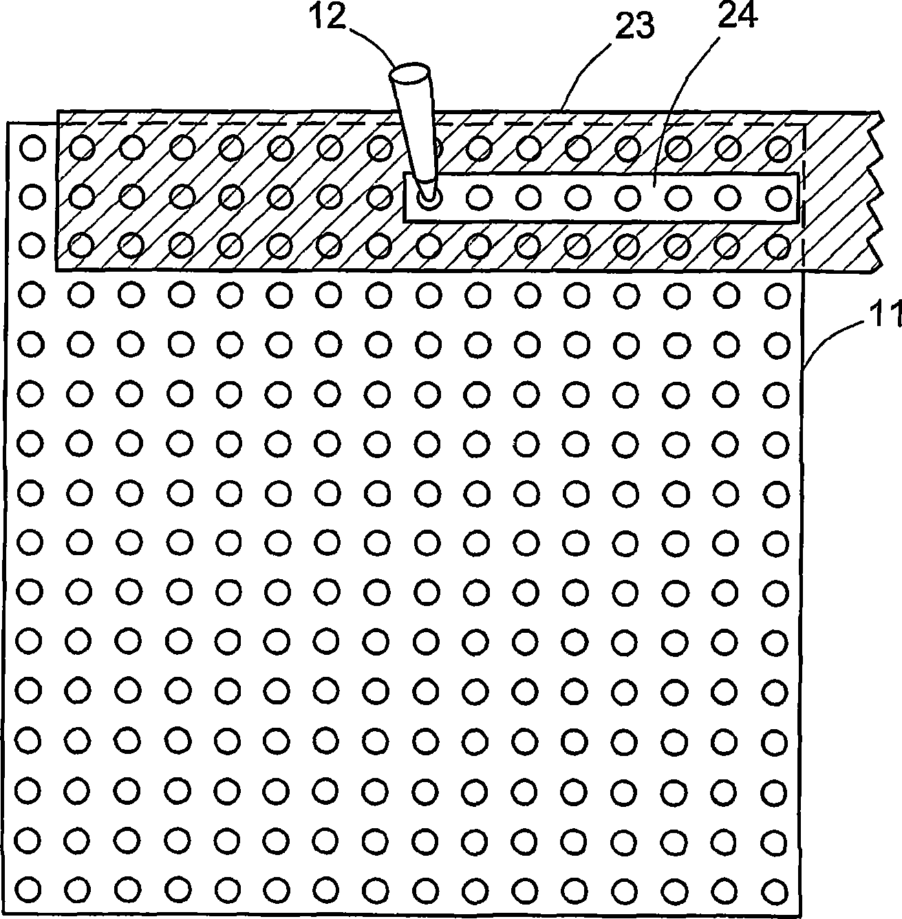
[0009] In this paper, the order of the positions of the microarray illuminated by the light source in the scanning process is called the scanning protocol, and the length of each process of the scanning head is determined in the round-trip process (the length from the scanning head to the light source is fixed ), for example, the back-to-front movement of the scan head, which also incorporates the microarray incremental movement that enables the scan head to align with the next row of sample positions on the microarray and the scan head, mask, and complete microarray scan All other movements of the microarray are required. While individual protocols can vary depending on the structure and dimensions of the microarray, all protocols involve the reciprocation of the scan head along the x-axis to each row of the microarray. Absolute uniformity cannot be achieved while uniform scan head speed provides the most uniform distribution of illumination between sample positions along the...


PUM


Abstract

Scanning of a microarray is performed through a mask that exposes a plurality, but not all, of the sites of the microarray, and either the mask is movable relative to the microarray or the microarray is movable relative to the mask, or both. The mask is useful as a means of restricting the illumination of sites on the microarray to those that can be illuminated while the scan head is traveling at a steady, target velocity, blocking the passage of light between the scan head and the microarray at those points in the scan head trajectory where the scan head is either accelerating or decelerating. The mask is also useful for reducing background noise in the microarray image by preventing light spillage to sites adjacent to those being scanned.

Description

technical field [0001] The present invention relates to scanning systems for biological type microarrays such as nucleic acids and proteins, and generally to illumination systems for any type of process involving the individual and sequential illumination of a large number of locations arranged in a spatial array . Background technique [0002] A microarray is a two-dimensional array of sites where chemical and biochemical assays are performed, generally each site has a microscopic size that allows for an individual assay and typically has a different molecular species at each site. Microarrays can be formed on a variety of different substrates, including glass slides, microtiter plates, and membranes. Microarrays are commonly used, for example, in binding assays to identify, determine binding affinities in unknown biological species or their fundamental properties. Site size, number and spacing can vary significantly within a microarray. When the location is a well in a ...

Claims


Application Information

Patent Timeline
Patent Type & Authority Applications(China)
IPC IPC(8): H04N1/04G01J1/58G01N21/63G02B26/10
CPCG01N2201/1042G01N21/253G01N2201/0446
Inventor D·Y·楚
Owner BIO RAD LAB INC
Learn More