
CAE optimization method for radiation noise of battery pack shell of electric vehicle

A technology for electric vehicle batteries and radiation noise, applied in geometric CAD, battery pack components, design optimization/simulation, etc. Noise, well-designed effects

Pending Publication Date: 2022-07-05
CHONGQING COLLEGE OF ELECTRONICS ENG
View PDF0 Cites 0 Cited by
  • Summary
  • Abstract
  • Description
  • Claims
  • Application Information

AI Technical Summary

Problems solved by technology

[0003] For electric vehicles, the battery pack is installed under the floor of the body, forming a reverberation field with the body, and the radiation noise from the road noise passing through the battery pack case is amplified, resulting in increased noise inside the car

Method used


Image

  • CAE optimization method for radiation noise of battery pack shell of electric vehicle
  • CAE optimization method for radiation noise of battery pack shell of electric vehicle
  • CAE optimization method for radiation noise of battery pack shell of electric vehicle

Examples


Embodiment 1

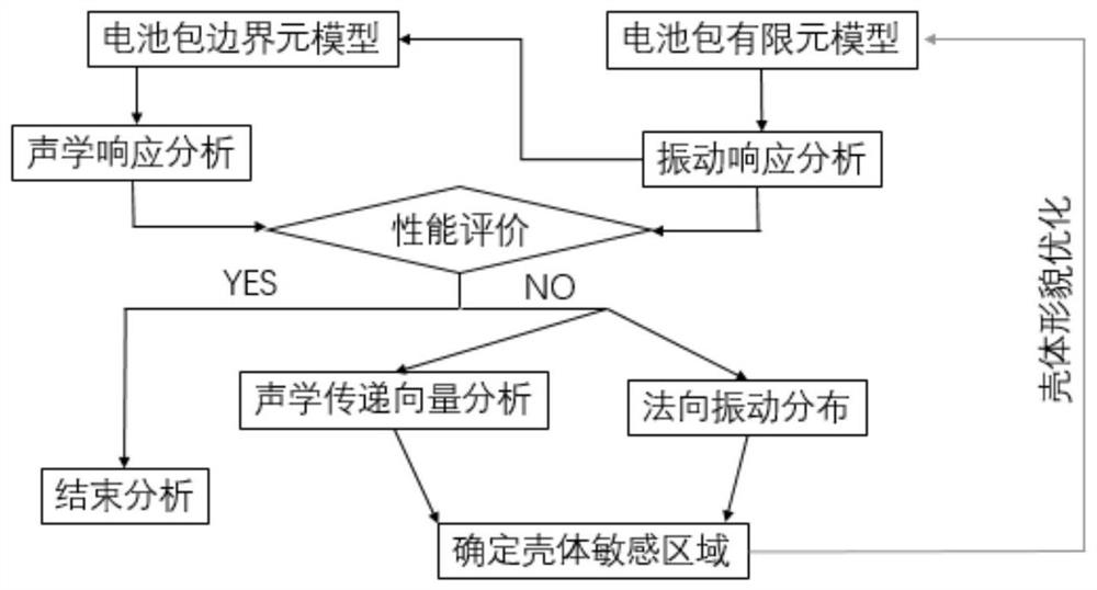
[0041] CAE optimization method for radiated noise of electric vehicle battery case, such as figure 1 Shown: Includes:

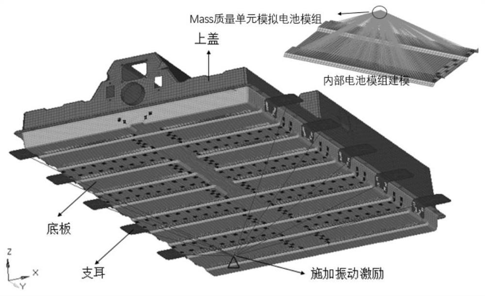
[0042] Step 1: Import the 3D geometric model of the electric vehicle battery pack to be optimized, and model the upper cover, bottom plate and lugs of the electric vehicle battery pack with plate-shell units, such as CAD model, and import the 3D geometric model into Hypermesh software to establish The finite element model of the battery pack of the electric vehicle battery pack as a whole, the internal battery module is simulated by the mass mass unit and the rigid rigid body unit, and the connecting bolts between the lug and the body longitudinal beam are simulated by the rigid rigid unit, and the finite element model of the battery pack is obtained. like figure 2 shown.

[0043]Step 2, apply a unit sinusoidal vibration excitation of 0-200Hz to the Z direction at the rigid main node. The unit sinusoidal vibration excitation refers to the 0-200Hz sweep fre...

Embodiment 2

[0051] The difference between the CAE optimization method for the radiated noise of the battery pack casing of an electric vehicle and the first embodiment is that it further includes step 4, calculating the radiated noise performance of the redesigned battery pack casing to verify the effectiveness of the optimization scheme. To obtain the sound power level of radiated noise before and after optimization, see Figure 11 . Depend on Figure 11 It can be seen that after the optimization of the upper cover stiffener, the 250Hz and 400Hz radiation noise peaks are reduced by 15.4dB and 3.8dB respectively, and the noise reduction effect is obvious. At the same time, the noise in the 500-650Hz frequency band has been improved overall. This shows that the shape optimization method described by the expression of the constraint condition and the expression of the response function of the normal vibration velocity of the key point is an effective measure to improve the radiated noise ...


PUM


Abstract

The invention relates to the technical field of computer aided design for electric vehicles, in particular to an electric vehicle battery pack shell radiation noise CAE (computer aided engineering) optimization method, which comprises the following steps of: 1, establishing a battery pack finite element model of the whole electric vehicle battery pack; 2, performing vibration response analysis on the finite element model of the battery pack, and estimating a battery pack radiation noise model of a battery pack shell to obtain vibration parameters; and step 3, through a morphology optimization method, redesigning the reinforcing rib layout of the area with the larger acoustic transmission vector and the larger normal vibration speed of the battery pack shell by using the vibration parameters, and obtaining a morphology optimization cloud picture of the battery pack shell. According to the invention, the design of the battery pack shell is more reasonable, and the radiation noise of the battery pack in the vehicle driving process is reduced.

Description

technical field [0001] The invention relates to the technical field of computer aided design for electric vehicles, in particular to a CAE optimization method for radiated noise of a battery pack casing of an electric vehicle. Background technique [0002] The diversified development of energy demand has promoted the development of electric vehicle technology that uses electric energy as a power source. The in-depth development of electric vehicle technology has made the quality of electric vehicles themselves widely concerned by consumers. NVH performance is the most important indicator to determine the quality of electric vehicles, so the NVH performance evaluation of electric vehicles is very important. When the electric vehicle is running, the excitation of the vibration source is transmitted to the thin-walled parts such as the casing of the powertrain and the body panel, which will induce radiated noise, which is the main source of NVH performance problems. [0003] F...

Claims


Application Information

Patent Timeline
Patent Type & Authority Applications(China)
IPC IPC(8): G06F30/23G06F30/15H01M50/244H01M50/249G06F119/10
CPCG06F30/23G06F30/15H01M50/244H01M50/249G06F2119/10Y02T90/00
Inventor 张宇熊先霖杨平
Owner CHONGQING COLLEGE OF ELECTRONICS ENG
Learn More