
Pressure filling device and method of molten metal

A technology of melting metal and pressure, applied in the direction of pressure vessels, pressure vessels/vacuum vessels used in chemical processes, etc., which can solve the problems of easy pollution and oxidation of metals, time-consuming and energy-consuming, pollution of people and the environment, etc.

Inactive Publication Date: 2011-05-11
BEIJING ALLWELLTECH
View PDF0 Cites 0 Cited by
  • Summary
  • Abstract
  • Description
  • Claims
  • Application Information

AI Technical Summary

Problems solved by technology

[0002] In thermometer calibration, some thermometers are calibrated using small fixed-point cells and fixed points. The existing methods for making small fixed-point cells and fixed points are generally to manually put indium, gallium, benzoic acid, and phenoxybenzene into the crucible. Then cover the crucible lid, then put the crucible into the bulb, seal the bulb, and then melt and evacuate. During this operation, very high-purity (more than 6 9) metals are easy to be polluted and oxidized, and easily Contaminate the operating people and the environment
Among these metals, some of their melting points are solids higher than room temperature, and some are close to or lower than normal temperature, which are very viscous liquids. Using the above filling methods is easy to damage the crucible, resulting in waste products and waste, which consumes time and energy.
It is not feasible to use the gravity method to fill the metal after heating. Since the inner diameter of the filling port is generally only about 2-3 mm, and the liquid metal has a high viscosity, it is not feasible to use the filling method relying on gravity, so it is urgently needed. A fast, convenient, time-saving and energy-saving device and method for making small fixed-point pools and fixed-point containers

Method used


Image

  • Pressure filling device and method of molten metal
  • Pressure filling device and method of molten metal

Examples


Embodiment Construction

[0021] Below with regard to the step and the structure and the effect that can produce of the pressure filling device and method of molten metal of the present invention, cooperate accompanying drawing to describe in detail as follows with preferred embodiment:

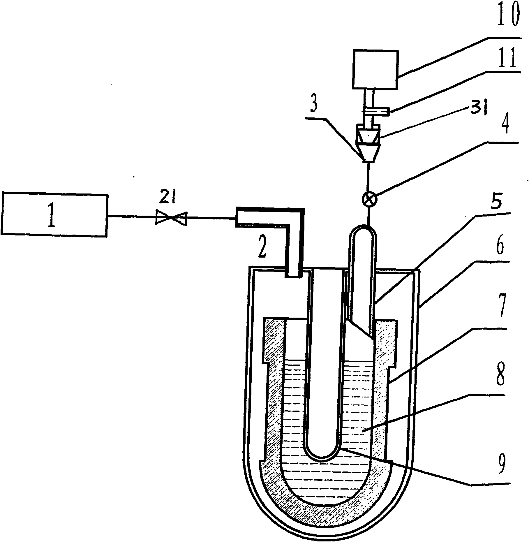
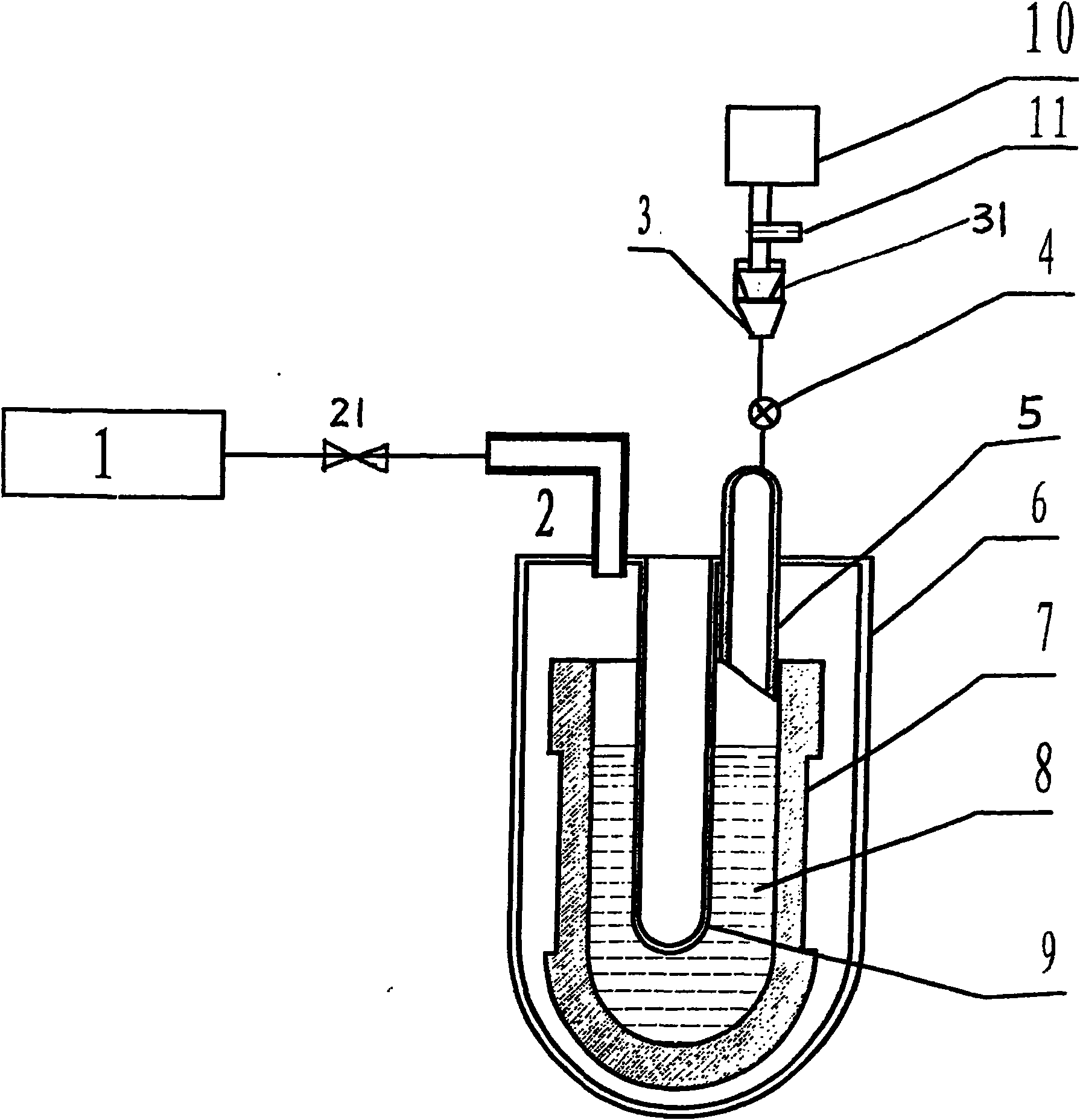
[0022] First referring to Fig. 1, the pressure filling device for molten metal of the present invention includes: vacuum system 1, exhaust pipe 2, funnel 3, valve 4, liquid filling pipe 5, bulb 6 (made of glass or metal, The following description takes the glass bulb as an example), crucible 7, thermometer well 9 and air bag 10; wherein the glass bulb 6 is "U" shaped, and the U-shaped opening is the thermometer well 9; the crucible 7 is arranged in the glass bulb 6, and the crucible 7. The opening is upward, and the opening end is provided with a distance from the upper port of the U-shaped tube. The bottom of the crucible 7 is placed on the U-shaped bottom of the glass bulb 6; The other end of the tube is connected t...


PUM


Abstract

The invention discloses a pressure filling device and a pressure filling method for molten metals. The pressure filling device for the molten metals mainly comprises a vacuum system, an exhaust pipe, a funnel, a valve, a liquid filling pipe, a glass cell-shell or a metallic cell-shell, a crucible, a thermometer well and a gas bag. The pressure filling method for the molten metals through the device comprises the following steps: firstly, performing leakage detection on a filling container; secondly, making the internal environment of the filling container form a positive pressure environment or a negative pressure environment, and infusing a metallic solution into the filling container; and finally, sintering and sealing a filling opening, and continuously performing vacuum exhaustion to make a triple-point small fixed-point pool container. The negative pressure method and the positive pressure method of the pressure filling method for the molten metals overcomes the defect of large viscosity of metal liquor, so that the problem of filling a metallic solution can be successfully solved, and a small fixed-point pool can be quickly and conveniently made with time and energy conversation.

Description

technical field [0001] The invention relates to a pressure filling device and method for molten metal, in particular to a device and method for automatically filling metal solution into a container through pressure difference. Background technique [0002] In thermometer calibration, some thermometers are calibrated using small fixed-point cells and fixed points. The existing method of making small fixed-point cells and fixed points is generally to manually put indium, gallium, benzoic acid, and phenoxybenzene into the crucible. Then cover the crucible lid, then put the crucible into the bulb, seal the bulb, and then melt and evacuate. In this operation process, very high-purity (more than 6 9) metals are easy to be polluted and oxidized, and easy to Make the operating people and the environment polluted. Among these metals, some of them are solids whose melting points are higher than room temperature, and some are very viscous liquids close to or lower than normal temperat...

Claims


Application Information

Patent Timeline
Patent Type & Authority Patents(China)
IPC IPC(8): B01J3/03
Inventor 王玉兰蒲耀立耿晨
Owner BEIJING ALLWELLTECH
Learn More