Electric accelerator pedal for vehicle

An electronic accelerator pedal and pedal arm technology, which is applied to the layout, transportation and packaging of vehicle components and power plant control mechanisms, can solve the problems of complex structure, poor cost-effectiveness, and many parts, and achieve a simplified and effective structure, and improve benefit, cost reduction effect

Active Publication Date: 2009-08-19
UNITED AUTOMOTIVE ELECTRONICS SYST
View PDF1 Cites 11 Cited by
  • Summary
  • Abstract
  • Description
  • Claims
  • Application Information

AI Technical Summary

Problems solved by technology

[0004] But on the whole, some of the current electronic accelerator pedals have no force-lag generating mechanism at all, cannot fully produce force-lag effects, and cannot provide the driving feeling of traditional mechanical pull-wire pedals; although some have force-lag generating mechanisms, their structures are relatively complicated. Lots of parts and poor cost-effectiveness

Method used


Image

  • Electric accelerator pedal for vehicle
  • Electric accelerator pedal for vehicle
  • Electric accelerator pedal for vehicle

Examples


Embodiment Construction

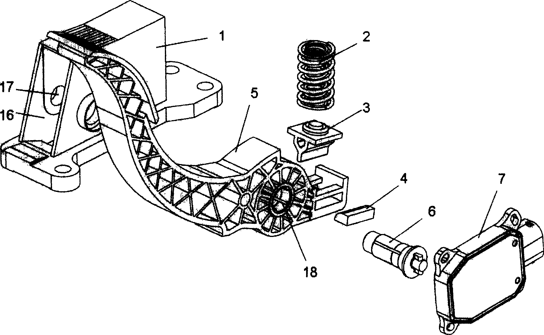
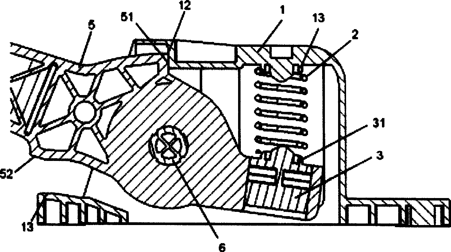
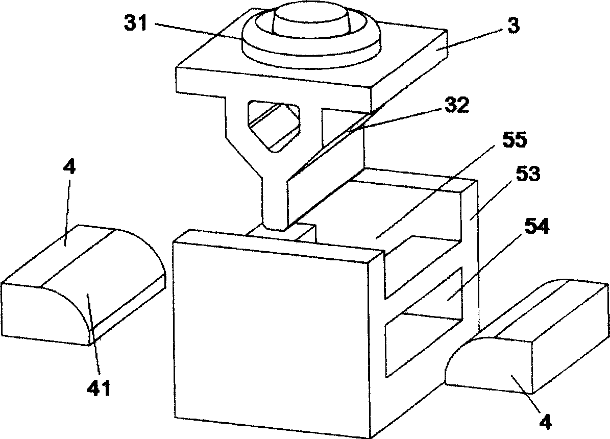
[0019] see figure 1 , 2 As shown, the electronic accelerator pedal of the present invention includes a housing 1 , a pedal arm 5 , a spring 2 , a spring support 3 , two friction elements 4 , a rotating shaft 6 and a sensor module 7 .

[0020] The front end of the housing 1 has an opening 16 , and the left and right side walls are provided with shaft holes 17 . The tail of the pedal arm 5 is provided with a shaft hole 18 . Insert the pedal arm 5 into the housing 1 from the opening 16 of the housing 1, the left and right direction is limited by the inner wall of the housing 1, and then the rotating shaft 6 is inserted into the shaft hole 17 of the housing 1 and the rotating shaft hole 18 of the pedal arm 5, so that The pedal arm 5 is installed in the housing 1 and can be rotated. The rotating shaft 6 can be a stepped shaft, and at this time, the rotating shaft 6 can only be inserted into the pedal arm 5 through the opening 16 on one side of the housing 1 . Through the radial...


PUM


Abstract

The invention discloses an electronic accelerator pedal. The tail end of a pedal arm is provided with a force lag generating mechanism which comprises a base, two friction elements, a spring support and a spring; the two friction elements are arranged on two sides of the base, the spring support is arranged in an open slot at the upper end of the base, and the upper end face of the spring support is provided with a spring retainer which is arranged between a spring retainer of the spring support and a second spring retainer on a shell; and the lower end of the spring support is a wedge with a wide upper part and a narrow lower part, and two inclined planes at the lower end of the wedge are contacted with the end faces of the friction elements. The electronic accelerator pedal can generate good force lag effect and has good cost effectiveness.

Description

technical field [0001] The invention relates to an engine system of an automobile, in particular to an electronic accelerator pedal suitable for various vehicles. Background technique [0002] Most of the existing traditional accelerator pedals are connected to the fuel subsystem of the engine by a stay wire, and the valve opening is directly controlled by the stay wire. Based on the concept of drive-by-wire (wire-by-wire), it is the future development trend in the automotive field to replace the traditional pull-wire pedal with an electronic accelerator pedal. In a fully electronic accelerator pedal, a position sensor is used to reflect the position of the accelerator pedal and transmit the position signal to the throttle controller. Sensor-based accelerator pedals are particularly well suited for electronically controlled systems, where accelerator pedal position is one of the engine's controlled variables. [0003] For the friction between the cable and its protective c...

Claims


Application Information

Patent Timeline
IPC IPC(8): B60K26/02
Inventor 过于成王慕昊焦兴军彭禹
Owner UNITED AUTOMOTIVE ELECTRONICS SYST
Why Eureka
Try Eureka