
Cooling structure for belt type stepless change

A technology of continuously variable transmission and cooling structure, which is applied in the directions of gear lubrication/cooling, belt/chain/gear, mechanical equipment, etc. It can solve the problems of complex shape of parts, adverse effects on appearance, and large number of parts, etc., and achieve improved appearance , improved appearance, and the effect of reducing the number of parts

Inactive Publication Date: 2012-03-21
HONDA MOTOR CO LTD
View PDF1 Cites 0 Cited by
  • Summary
  • Abstract
  • Description
  • Claims
  • Application Information

AI Technical Summary

Problems solved by technology

[0006] In this way, in the cooling structure of the belt-type continuously variable transmission of Patent Document 1, a duct for introducing external air is formed, and an umbrella is specially provided in order to cover the external air introducing port at the front end, so the number of components is large and the shape of the components is large. Complicated and large-scale, which will adversely affect the appearance

Method used


Image

  • Cooling structure for belt type stepless change
  • Cooling structure for belt type stepless change
  • Cooling structure for belt type stepless change

Examples


Embodiment Construction

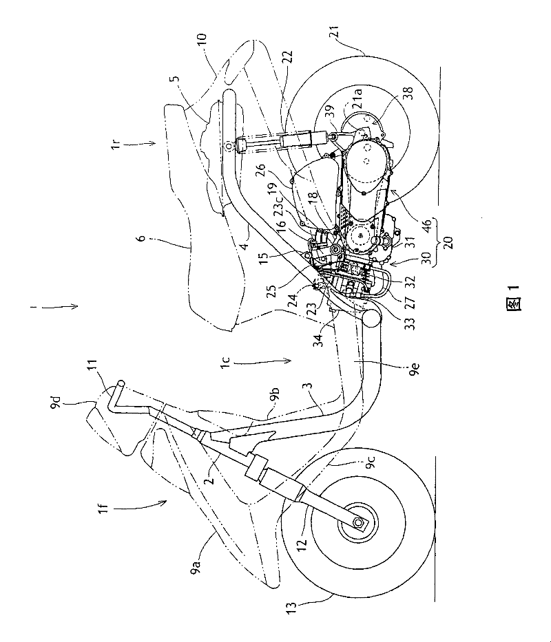
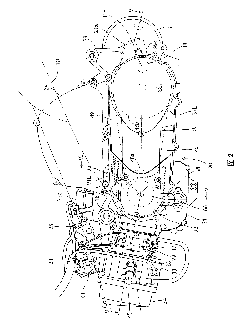
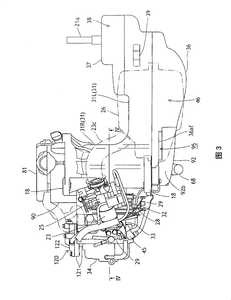
[0055] based on the following Figure 1 to Figure 11 One embodiment of the present invention will be described.

[0056] figure 1 It is a side view of the scooter-type motorcycle 1 to which the embodiment of the present invention is applied.

[0057] The front part 1f of the vehicle body and the rear part 1r of the vehicle body are connected via a low bottom part 1c, and the vehicle body frame constituting the frame of the vehicle body is roughly composed of a lower tongue 3 and a main pipe 4 .

[0058] That is, a frame lower tongue 3 extends downward from the head pipe 2 of the front portion 1f of the vehicle body. The frame lower tongue 3 is bent horizontally at the lower end, extends backward through the bottom 1c, and connects the left and right sides at the rear end. The pair of main pipes 4 rises obliquely rearward from the connecting portion, bends horizontally at a predetermined height, and extends rearward.

[0059] A fuel tank 5 and the like are supported by the m...


PUM


Abstract

This invention relates to a cooling structure of a continuously variable belt transmission, being capable of preventing invasion of water or ash, advanced with a small quantity of components, small and simple structure, and beautiful appearance. In a power unit (20) installed in an automatic bicycle, a continuously variable belt transmission (46) is covered, while a transmission case cover (36) covers the transmission case (31L) from a side so as to form a speed change chamber (46C); a cooling fan (48F) is disposed on a shaft end of a crank shaft (40); a cooling air guide-in hole (36i) is disposed on a part of the transmission case cover (36) in correspondence with the cooling fan (48F), so as to guide the cooling air to the speed change chamber (46C), where the cooling air guide-in hole (36i) of the transmission case cover (36) and periphery thereof are covered from a side by a side cover part (92); an outer air guide-in hole (95) with an opening upwards is disposed on the end face of circumferential wall of the side cover part (92) and the joint part of the transmission case cover (36).

Description

technical field [0001] The present invention relates to a cooling structure for a belt-type continuously variable transmission of a power unit mounted on an automatic two-wheel vehicle. Background technique [0002] The cooling structure of such a belt-type continuously variable transmission installed in a vehicle-mounted power unit is known. The belt-type continuously variable transmission is provided on the side of the transmission case that doubles as a crankcase that supports the crankshaft of the internal combustion engine and makes it rotatable, and the belt is covered. The transmission case cover is covered on the transmission case from the side of the type continuously variable transmission to form a transmission chamber, wherein the cooling air inlet formed on the part of the transmission case cover facing the cooling fan is covered with a cover member, and the cover An external air inlet is formed on the member (for example, refer to Patent Document 1). [0003] P...

Claims


Application Information

Patent Timeline
Patent Type & Authority Patents(China)
IPC IPC(8): F16H57/04F16H57/035B60K17/06
CPCB60K13/02F16H9/00F16H57/0415
Inventor 土屋粒二堀井宣孝
Owner HONDA MOTOR CO LTD
Learn More