Composite phase mask plate

A phase mask, composite technology, used in television, optics, instruments, etc., can solve problems such as reducing resolution and sacrificing system light throughput, and achieve the effect of small information curve and good depth of field expansion capability.

Inactive Publication Date: 2009-08-19
ZHEJIANG UNIV
View PDF1 Cites 23 Cited by
  • Summary
  • Abstract
  • Description
  • Claims
  • Application Information

AI Technical Summary

Problems solved by technology

Studies have shown that changing the shape of the aperture can create a good effect of large depth of field, but this effect is achieved at the expense of sacrificing the amount of light through the system and reducing the resolution

Method used


Image

  • Composite phase mask plate
  • Composite phase mask plate
  • Composite phase mask plate

Examples


Embodiment Construction

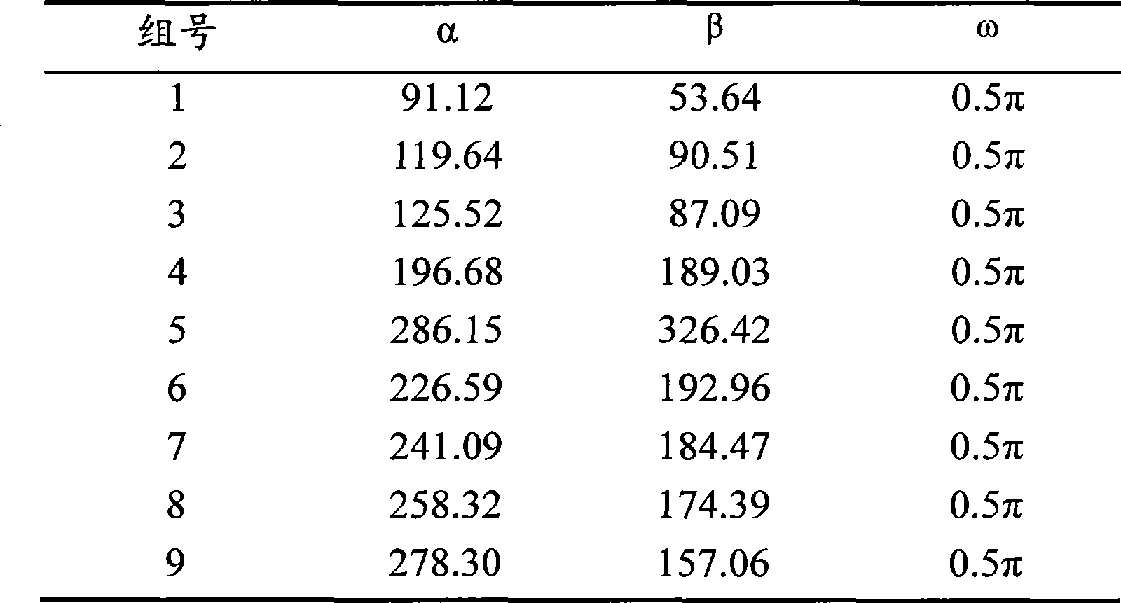
[0024] A composite phase mask, the phase distribution function of the composite phase mask includes two functions of sinusoidal and cubic, and the function of the phase distribution function θ (x, y) is as follows:

[0025] θ(x,y)=α·(x 3 +y 3 )+β·(sin(ω·x)+sin(ω·y))

[0026] In the formula, β·(sin(ω·x)+sin(ω·y)) is a sinusoidal function, α·(x 3 +y 3 ) is a cubic function; where α is the magnitude of the cubic function, β is the magnitude of the sinusoidal function, ω represents the angular frequency of the sinusoidal function, and x, y are the normalized space coordinates of the aperture plane.

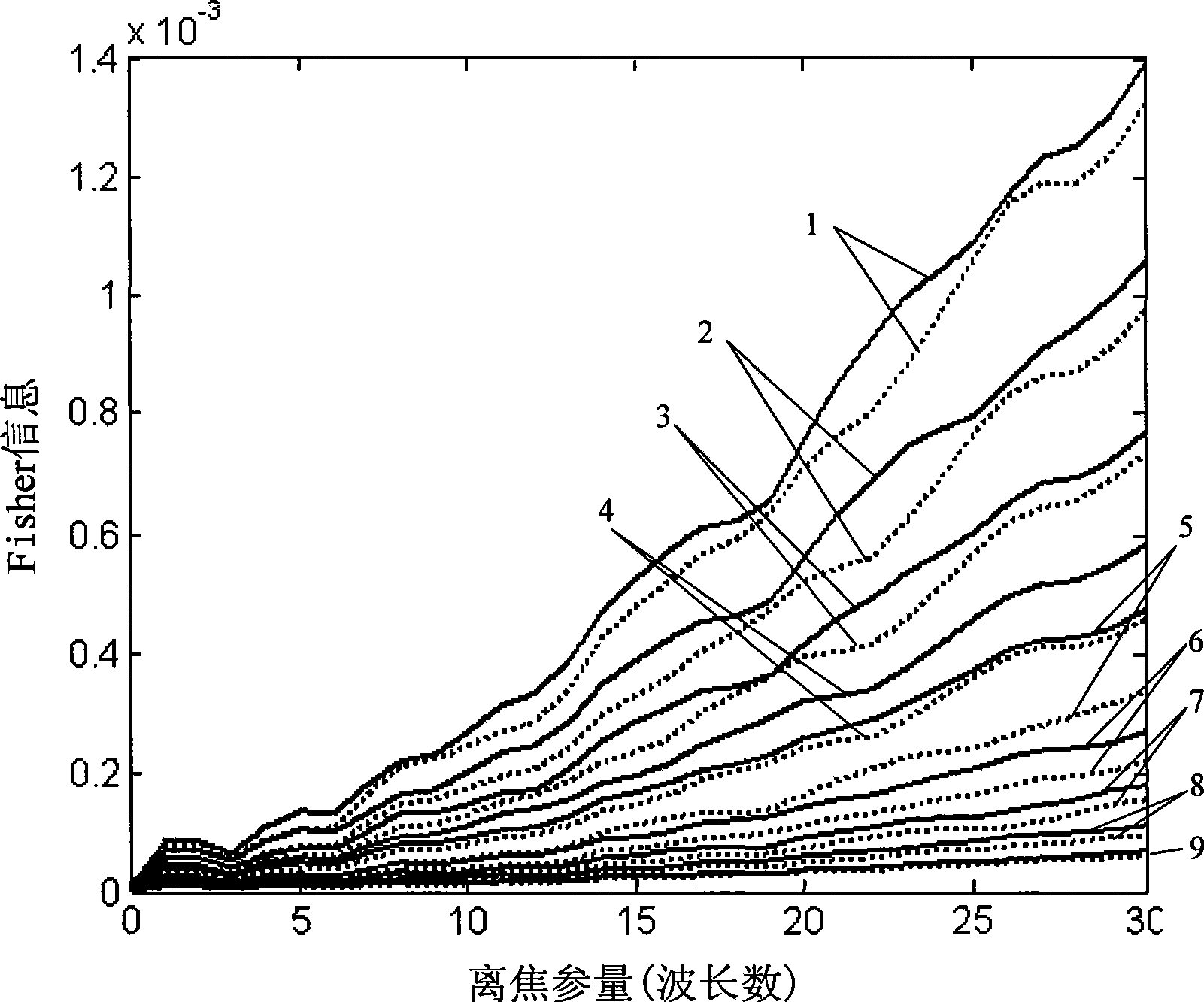
[0027] The surface shape of a composite phase mask of the present invention and the surface shape of the exponential phase mask are compared in the appended figure 2 , the surface shape of a composite phase mask of the present invention is attached figure 2 Indicated by the dotted line, the surface shape of the exponential phase mask is in the attached figure 2 Indicated by a...


PUM


Abstract

The invention discloses a composite phase mask, the phase distribution function of which contains two different functions, namely, a sinusoidal type function and a third power type function. The function expression of the phase distribution function Theta(x, y) is as follows: Theta(x, y) is equal to Alpha question mark (x plus y) plus Beta question mark (sin(Omega question mark x) plus sin(Omega question mark y)), and in the expression, Beta question mark (sin(Omega question mark x) plus sin(Omega question mark y)) is a sinusoidal type function, and Alpha question mark (x plus y) is a third power type function; wherein Alpha is the amplitude of the third power type function, Beta is the amplitude of the sinusoidal type function, Omega expresses the angular frequency of the sinusoidal type function, and x, y is space coordinate with normalized aperture plane. The invention also discloses an imaging system which adopts the composite phase mask compounded by the sinusoidal type function and the third power type function and has smaller numerical value of the Fisher information, and the phase mask is not sensitive to defocusing, thus having better expansion capability of depth of focus.

Description

technical field [0001] The invention relates to a phase mask, in particular to a composite phase mask in which two functions of a cubic type and a sinusoidal type are compounded Background technique [0002] As we all know, any optical system has a certain depth of field, and only objects within the depth of field can be clearly imaged, while the image formed by the optical system of objects beyond the depth of field will become blurred, resulting in the loss of details and textures . [0003] As early as 1960, W.T. Welford discussed the possibility of extending the depth of field of an optical system by using an annular aperture, that is, a central obscuration method. In 1987, Ting-Chung Poon and Masoud Motamedi, based on the use of annular apertures, relied on digital image restoration algorithms to actually verify the effect of depth-of-field expansion. During the period from the late 1980s to the early 1990s, Ojeda-Castaneda Jorge et al. Using the classic apodization m...

Claims


Application Information

Patent Timeline
Patent Type & Authority Applications(China)
IPC IPC(8): G02B27/46H04N5/225
Inventor 李奇赵惠冯华君徐之海
Owner ZHEJIANG UNIV
Why Eureka
Try Eureka