Wound rotor brushless double fed motor

A doubly-fed motor, wound rotor technology, applied in asynchronous induction motors, windings, electromechanical devices, etc., can solve problems such as large size and performance gaps

Active Publication Date: 2009-08-19
WUHAN YANGHUA ELECTRIC CO LTD
View PDF0 Cites 31 Cited by
  • Summary
  • Abstract
  • Description
  • Claims
  • Application Information

AI Technical Summary

Problems solved by technology

Because the iron core of the reluctance rotor must be made into a structure similar to salient poles, and the winding of the cage-type short-circuit winding rotor must be made into concentric distributed short-circuit windings. Under the constraints of these conditions, these two types of rotors can only be used for specific applications. The number of poles, and the performance index is quite different from that of the conventional AC motor rotor, and the volume is also larger, etc.

Method used


Image

  • Wound rotor brushless double fed motor
  • Wound rotor brushless double fed motor
  • Wound rotor brushless double fed motor

Examples


Embodiment Construction

[0045] The implementation of the present invention is illustrated below with examples.

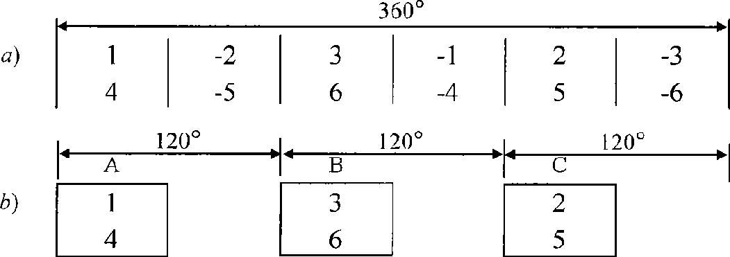
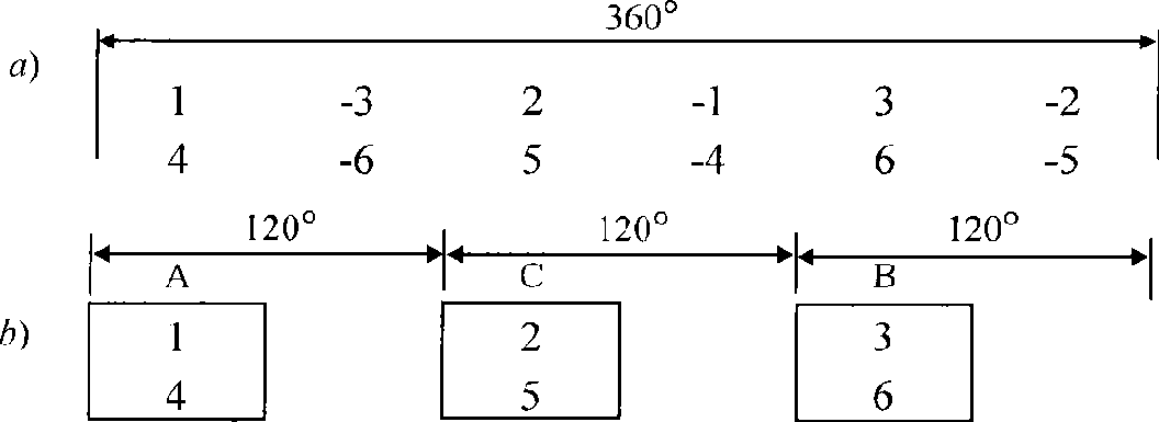
[0046] There is a tooth harmonic brushless doubly-fed motor rotor, the number of pole pairs of its power winding is p 1 = 4, select the number of pole pairs of the control winding as p 2 =2, according to the relationship Z=p 1 +p 2 Select the number of rotor slots as Z=p 1 +p 2 =6, and according to the relationship m=Z / m k =(p 1 +p 2 ) / m k (m k =1, when Z is an odd number; m k =2, when Z is an even number), it can be seen that the rotor winding phase number m=Z / m k =6 / 2=3.

[0047] For Z=6, p 1 = 4,p 2 = 2, m = 3 rotor winding, if you want to get the specific wiring method, you can first draw the slot number phase diagram, such as figure 1 As shown in a), it can be determined that the slot number distribution of each phase is as follows figure 1 As shown in b), it can be seen that for p 1 = 4 is a three-phase winding, if the coil span y = 1, then the distribution coefficien...


PUM


Abstract

The invention discloses a brushless doubly-fed motor of a wound rotor, pertaining to the technical field of motors. In an AC (alternating current) brushless doubly-fed motor of the invention, two sets of three-phase windings with respective numbers of pole pairs as P1 and p2 are arranged on a stator; a rotor adopts a multi-phase winding and a phase number m meets the relational expression: m= (P1 + p2) / mk, wherein, when P1+ p2 is an odd number, mk is equal to 1; when P1 + p2 is an even number, and mk is equal to 2 and rotor slots are uniformly distributed along the circumference of an air gap. Number of rotor slots Z' meets the relational expression: Z'=n (P1 + p2), wherein, n is a positive number; coils of rotor winding are multi-turn structures; the coil number of each phase winding is nmk; the span of each coil is equal but the specific value of turn number between the coils is different; and when the number of coils of the phase windings is less than or equal to nmk, all coils in phase windings are coupled when in short circuit after being series-connected. The brushless doubly-fed motor has the advantages that the span of winding coil can be flexibly changed and the turn number of each coil can be different, thereby realizing the purpose of maximally reducing the higher harmonic.

Description

technical field [0001] The invention belongs to the technical field of motors, and in particular relates to an AC brushless doubly-fed motor designed by utilizing the harmonic magnetomotive force of rotor winding teeth. Background technique [0002] Those skilled in the art know very well that AC brushless doubly-fed motors are suitable for frequency conversion and speed regulation systems, and are characterized by reliable operation and small required frequency converter capacity. There are two sets of windings on the stator of this motor, and the number of pole pairs in one set is p 1 , another set of pole pairs is p 2 . When the stator winding p 1 Turn on the grid power supply, and the number of magnetic pole pairs is p 1 The rotating magnetic field, the induced current in the rotor produces p 1 In addition to the antipolar magnetic field, p 2 For the pole-to-pole magnetic field, these two pole-logarithmic magnetic fields have opposite directions of rotation relativ...

Claims


Application Information

Patent Timeline
Patent Type & Authority Applications(China)
IPC IPC(8): H02K3/46H02K3/28
CPCH02K3/28H02K17/165H02K3/12
Inventor 王雪帆舒迪宪
Owner WUHAN YANGHUA ELECTRIC CO LTD
Why Eureka
Try Eureka