Electrolytic-capacitor-free motor driving system and current control method and current control device thereof

A motor drive system, electrolytic capacitor technology, applied in the direction of motor generator control, electronic commutation motor control, control of electromechanical transmission, etc., can solve problems that are difficult to achieve, high power factor, difficult to solve high-order harmonics of power supply, etc. , to achieve the effect of suppressing high-order harmonics, improving power factor, and meeting the requirements of harmonics

Active Publication Date: 2017-05-10
QINGDAO HAIER AIR CONDITIONER GENERAL CORP LTD
View PDF5 Cites 7 Cited by
  • Summary
  • Abstract
  • Description
  • Claims
  • Application Information

AI Technical Summary

Problems solved by technology

[0003] Since the motor drive system without electrolytic capacitors does not have the electrolytic capacitors and boost devices used as energy storage devices in traditional motor drive systems, it is difficult to achieve a higher power factor and Solve the problem of high-order harmonics of power supply

Method used


Image

  • Electrolytic-capacitor-free motor driving system and current control method and current control device thereof
  • Electrolytic-capacitor-free motor driving system and current control method and current control device thereof
  • Electrolytic-capacitor-free motor driving system and current control method and current control device thereof

Examples


Embodiment Construction

[0054] In order to make the object, technical solution and advantages of the present invention clearer, the present invention will be further described in detail below in conjunction with the accompanying drawings and embodiments.

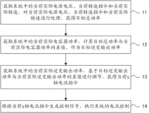
[0055] See figure 1 , which is a flow chart of an embodiment of the current control method of the electrolytic capacitor motor drive system based on the present invention.

[0056] Such as figure 1 As shown, the method for realizing the current control of the electrolytic capacitor motor drive system in this embodiment includes a process consisting of the following steps:

[0057] Step 11: Obtain the current actual power supply voltage, the current rotational speed command and the current actual rotational speed in the system, process the current actual power supply voltage, the current rotational speed command and the current actual rotational speed, and obtain the target total power.

[0058]The current actual power supply voltage can be obtain...


PUM


Abstract

The invention discloses an electrolytic-capacitor-free motor driving system and a current control method and a current control device thereof. The method comprises the following steps: obtaining current actual supply voltage, current rotating speed command and current actual rotating speed in the system, processing the current actual supply voltage, the current rotating speed command and the current actual rotating speed, and obtaining target total power; obtaining current actual capacitor power in the system, calculating the difference value of the target total power and the current actual capacitor power as target inverter output power; obtaining current actual inverter output power in the system, adjusting the current actual inverter output power based on the difference value of the target inverter output power and the current actual inverter output power, and obtaining current q-axis current command; generating a control signal according to the current q-axis current command, and executing current control of the system. By using the method, the purposes of improving the power factor of the electrolytic-capacitor-free motor driving system and inhibiting higher harmonics can be achieved.

Description

technical field [0001] The invention belongs to the technical field of electric motors, and in particular relates to a non-electrolytic capacitor electric motor drive system and its current control method and control device. Background technique [0002] With the continuous improvement of users' performance requirements for electromechanical products, electrolytic capacitor motor drive systems with higher life expectancy, higher efficiency and lower cost have been more and more widely used. The non-electrolytic capacitor motor drive system removes the large-capacity, high-cost, and short-life electrolytic capacitors and boost devices, and replaces them with small-capacity, low-cost, and long-life film capacitors or ceramic capacitors. [0003] Since the motor drive system without electrolytic capacitors does not have the electrolytic capacitors and boost devices used as energy storage devices in traditional motor drive systems, it is difficult to achieve a higher power facto...

Claims


Application Information

Patent Timeline
Patent Type & Authority Applications(China)
IPC IPC(8): H02P21/22H02P21/18
CPCH02P21/0003
Inventor 许国景刘聚科程永甫
Owner QINGDAO HAIER AIR CONDITIONER GENERAL CORP LTD
Why Eureka
Try Eureka