Microstrip fed harmonic suppression broadband patch antenna with compact structure

A microstrip feeding and harmonic suppression technology, applied in antennas, slot antennas, radiating element structures, etc., can solve the problems of narrow bandwidth and increase the overall size of the antenna system, achieve small size, suppress high-order harmonics, The effect of increasing bandwidth

Inactive Publication Date: 2018-09-25
NANJING UNIV OF SCI & TECH
View PDF4 Cites 7 Cited by
  • Summary
  • Abstract
  • Description
  • Claims
  • Application Information

AI Technical Summary

Problems solved by technology

Despite these advantages, microstrip patch antennas have an inherent disadvantage: narrow bandwidth
[0004] At present, considering the harmonic radiation, the most simple and direct method is to connect a filter on the patch antenna, but this will increase the overall size of the antenna system

Method used


Image

  • Microstrip fed harmonic suppression broadband patch antenna with compact structure
  • Microstrip fed harmonic suppression broadband patch antenna with compact structure
  • Microstrip fed harmonic suppression broadband patch antenna with compact structure

Examples


Embodiment

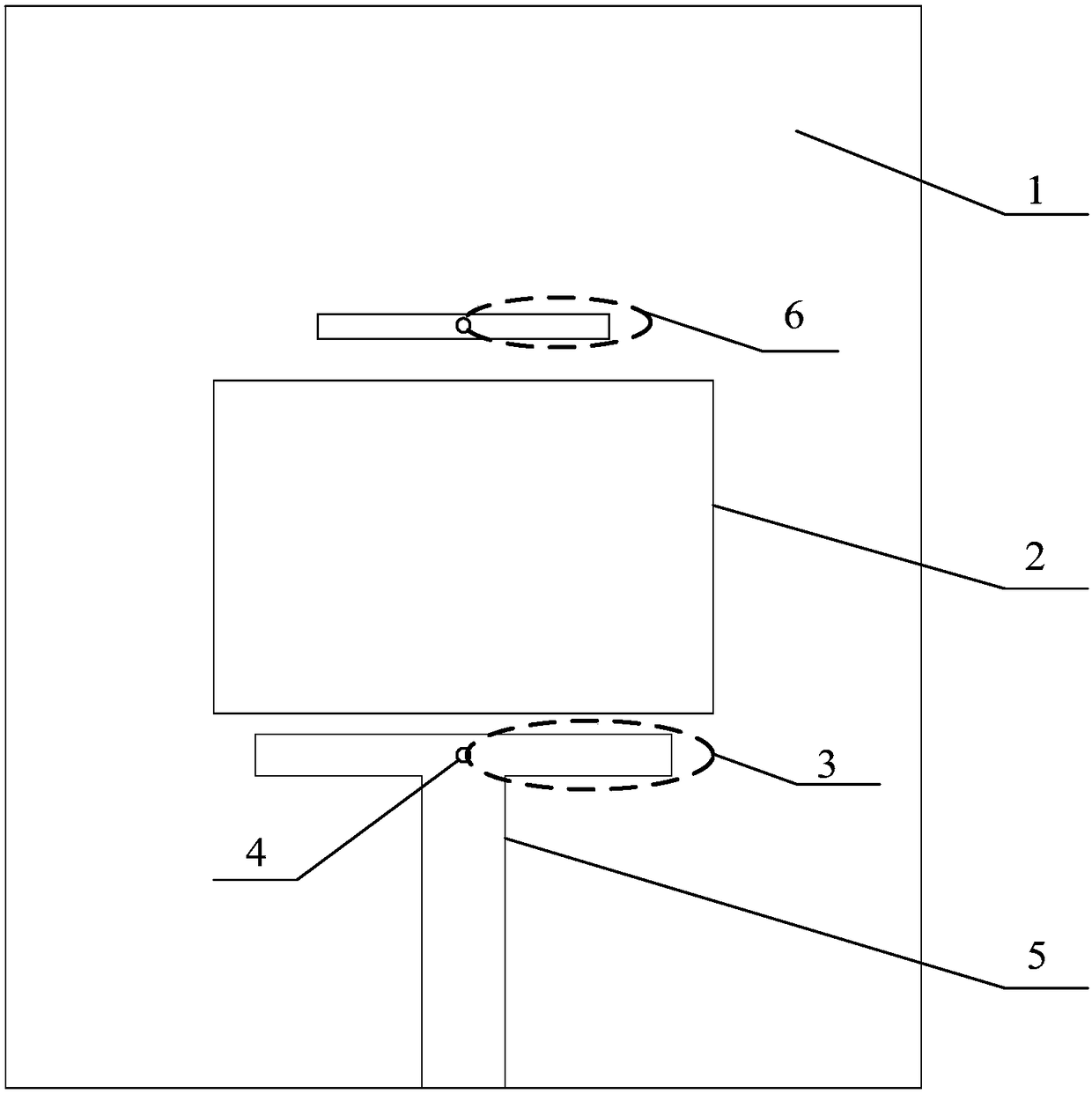
[0029] In the example design made, the size of the selected microstrip antenna is 60mm×60mm, the working frequency of the microstrip antenna is 4.9GHz, the size of the rectangular radiation patch is 30mm×17.5mm, and the working frequency is f 2 The quarter-wavelength resonator has dimensions of 10.7 mm × 0.5 mm and is located 1.55 mm away from the rectangular radiating patch at an operating frequency of f 3 The size of the quarter-wavelength resonator is 9.05mm×1.1mm, the distance from the rectangular radiation patch is 4.75mm, and the radius of the shorting pin is 0.5mm. The antenna dielectric plate adopts Rogers Duroid 5870 commercial plate with a dielectric constant of 2.33, a loss tangent of 0.0012, and a thickness of 1.57 mm.

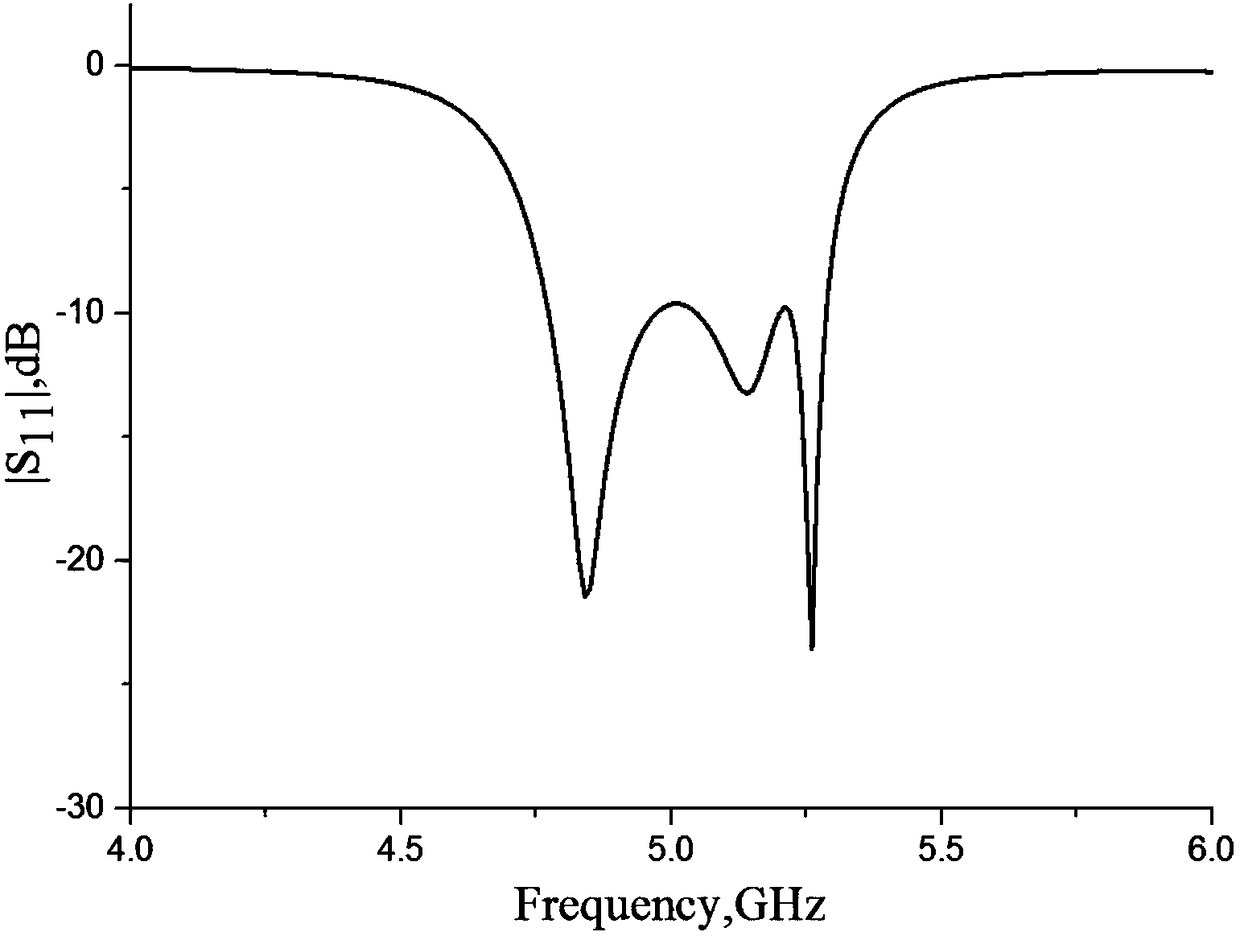
[0030] see figure 2 , is the harmonic suppression broadband patch antenna S 11 parameter, the antenna bandwidth covers 4.77-5.3GHz (10.8%).

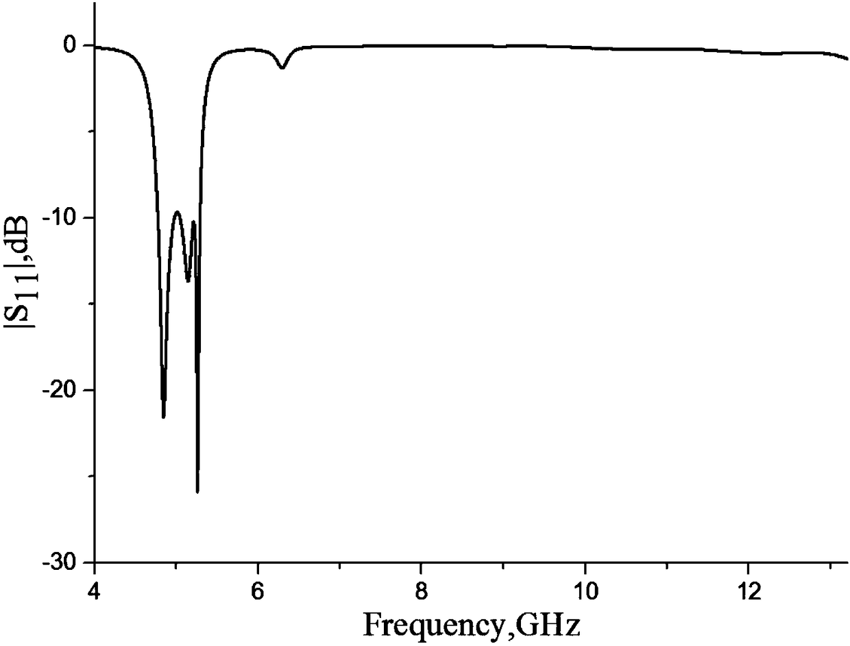
[0031] see image 3 , for the harmonic suppression broadband patch antenna with compact structure mic...


PUM


Abstract

The invention discloses a microstrip fed harmonic suppression broadband patch antenna with a compact structure. The broadband patch antenna comprises a single-layer microwave dielectric substrate, a rectangular radiation patch with a working frequency of f1, two quarter-wavelength resonators with a working frequency of f2, two quarter-wavelength resonators with a working frequency of f3, two short-circuit pins with a radius of r and a feeding microstrip line, wherein the rectangular radiation patch with the working frequency of f1 is located at the center of the whole structure; the two quarter-wavelength resonators with the working frequency of f2 share one short-circuit pin with the radius of r, are in near-coupling with a radiation edge of the rectangular radiation patch and are connected with the microstrip line to realize a feeding structure; and the two quarter-wavelength resonators with the working frequency of f3 share one short-circuit pin with the radius of r and are in near-coupling with another radiation edge of the rectangular radiation patch. The bandwidth of the patch antenna is effectively increased, high-order harmonic waves can be effectively suppressed, and the broadband patch antenna is compact and simple in structure, low in profile and easy to implement.

Description

technical field [0001] The invention belongs to the technical field of antennas, in particular to a harmonic suppression broadband patch antenna with compact structure and microstrip feeding. Background technique [0002] In modern communication and radar systems, antennas and front ends are placed closely together, or even integrated. In these systems, the microstrip patch antenna is very popular because it can be easily integrated with many other active and passive circuits, such as filters, amplifiers, oscillators, and mixers. Despite these advantages, microstrip patch antennas have an inherent disadvantage: narrow bandwidth. The microstrip antenna is a resonant antenna. When the working frequency deviates from the resonant frequency of the antenna, the impedance matching of the antenna will deteriorate sharply, making the narrow bandwidth of the microstrip antenna a very important issue. [0003] There are several common ways to increase the bandwidth of the microstrip...

Claims


Application Information

Patent Timeline
Patent Type & Authority Applications(China)
IPC IPC(8): H01Q1/38H01Q13/08H01Q13/10
Inventor 张金栋吴翠翠冯敏陈峤羽汤普祥姚祺周雅莉梁琴琴施雁佳
Owner NANJING UNIV OF SCI & TECH
Why Eureka
Try Eureka