
Acoustic wave ranging method and device

A sound wave ranging and sound wave technology, applied in the field of measurement, can solve the problems of poor reliability of ranging results, unable to detect echo loss and channel noise interference, unable to suppress the influence of wind speed, etc., to achieve detection of acoustic wave transmission channel interference and The effect of echo loss, overcoming initial waveform distortion, and achieving accurate statistics

Active Publication Date: 2018-09-21
LIAONING UNIVERSITY OF PETROLEUM AND CHEMICAL TECHNOLOGY
View PDF11 Cites 7 Cited by
  • Summary
  • Abstract
  • Description
  • Claims
  • Application Information

AI Technical Summary

Problems solved by technology

Since the amplitude of the echo is not only related to the distance, but also affected by multiple factors such as the degree of medium absorption and the environment, the accuracy compensation results of the variable reference voltage method are difficult to quantify
Moreover, due to the limitation of the measurement principle, the above method cannot well overcome the influence of wind speed on the measurement results
[0005] In summary, the main problems existing in the existing ranging methods can be summarized as follows: 1) They are all open-loop modes, and the system cannot detect echo loss and channel noise interference, so the reliability of the ranging results is poor; 2) It is difficult to quantify the trigger delay time caused by echo fluctuations in order to accurately compensate the ranging accuracy; 3) It is impossible to suppress the influence of wind speed on distance measurement

Method used


Image

  • Acoustic wave ranging method and device
  • Acoustic wave ranging method and device
  • Acoustic wave ranging method and device

Examples


Embodiment Construction

[0056] Exemplary embodiments of the present disclosure will be described in more detail below with reference to the accompanying drawings. Although exemplary embodiments of the present disclosure are shown in the drawings, it should be understood that the present disclosure may be embodied in various forms and should not be limited by the embodiments set forth herein. Rather, these embodiments are provided for more thorough understanding of the present disclosure and to fully convey the scope of the present disclosure to those skilled in the art.

[0057] In order to make the advantages of the technical solution of the present invention clearer, the present invention will be described in detail below in conjunction with the accompanying drawings and embodiments.

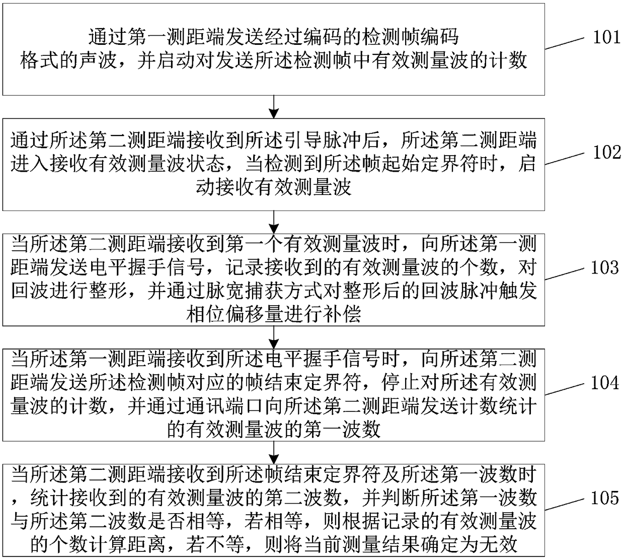
[0058] The embodiment of the present invention provides a method of sound wave ranging, such as figure 1 As shown, the method includes:

[0059] 101. Send the coded sound waves in the coding format of the detection...


PUM


Abstract

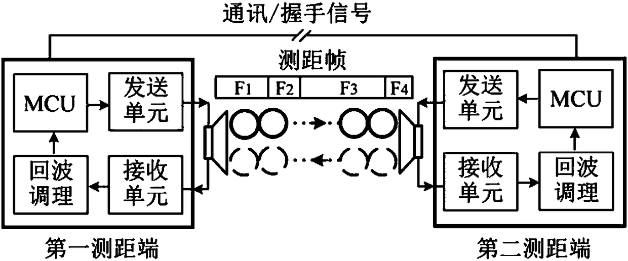
The invention discloses an acoustic wave ranging method and device, and relates to the technical field of measurement. The problems of poor measurement reliability and wind speed influence, which arecaused by echo loss and channel interference and the problem of ranging error caused by trigger phase shift caused by echo fluctuations in the existing acoustic wave ranging technology are overcome. According to the technology, a transmitting end sends encoded acoustic waves in a detection frame encoding format and starts effective measuring wave counting; a receiving end is in an acoustic wave receiving state after receiving a pilot code; after a frame start delimiter is detected, effective measuring wave counting is started; when a first effective measuring wave is received, a level handshake signal is sent to the transmitting end; after receiving the level handshake signal, the transmitting end sends a frame end delimiter, stops counting, and counts and transmits the number of the effective measuring waves; after receiving the frame end delimiter, the receiving end counts the number of actually received effective measuring waves; and if two numbers are equal, distance is calculatedbased on the relationship between the counted number of the effective measuring waves and the wavelength.

Description

technical field [0001] The invention relates to the field of measurement technology, in particular to a method and device for measuring distance using sound waves. Background technique [0002] Similar to infrared, laser and radio ranging, ultrasonic ranging is also a typical non-contact detection method. At the same time, sound waves also have low cost and are not disturbed by light, electromagnetic fields and other factors. Navigation and other industrial fields have been widely used. [0003] At present, from the perspective of measurement methods, ultrasonic range finders have two types: through-beam and reflective, among which the reflective is divided into two types: integrated transceiver and independent transceiver. As far as the measurement principle is concerned, there are mainly time-of-flight method, phase difference method and echo amplitude method. These three methods are all open-loop measurement methods. The main problem is that the system cannot detect the ...

Claims


Application Information

Patent Timeline
IPC IPC(8): G01S15/08
CPCG01S15/08
Inventor 白海城
Owner LIAONING UNIVERSITY OF PETROLEUM AND CHEMICAL TECHNOLOGY
Learn More