Supercharge Your Innovation With Domain-Expert AI Agents!

Variable frequency drive system and motor thereof

A variable frequency drive and motor technology, applied in the direction of AC motor control, control systems, electrical components, etc., can solve the problems of large number of inverter circuit units, insufficient utilization of component capacity, and lack of symmetry

Inactive Publication Date: 2009-08-19
江门金羚电机有限公司
View PDF3 Cites 1 Cited by
  • Summary
  • Abstract
  • Description
  • Claims
  • Application Information

AI Technical Summary

Problems solved by technology

[0002] The three-phase inverter drive three-phase motor system has been widely used in industrial equipment, but it is used for electric appliances powered by single-phase power supply with relatively small power. The inverter circuit appears to have too many units and insufficient component capacity.
But when the actual circuit is running, the test result of the effective value of the voltage on the three input terminals of the motor is that the voltage U of the two-phase inverter output terminals A and B to the common terminal C CA and U CB Roughly equal, but lower than the fundamental voltage U between the two output terminals AB Small; the test result of the effective value of the current entering the three input terminals of the motor is that the output current I of the two-phase inverter output terminals (controlled terminals) A and B A and I B Roughly equal, but higher than the current I of the common terminal (non-controlled terminal) sub-C C The ratio is larger, which means that it is still undersymmetrical, which has an impact on efficiency and vibration and noise levels

Method used


Image

  • Variable frequency drive system and motor thereof
  • Variable frequency drive system and motor thereof
  • Variable frequency drive system and motor thereof

Examples


Embodiment Construction

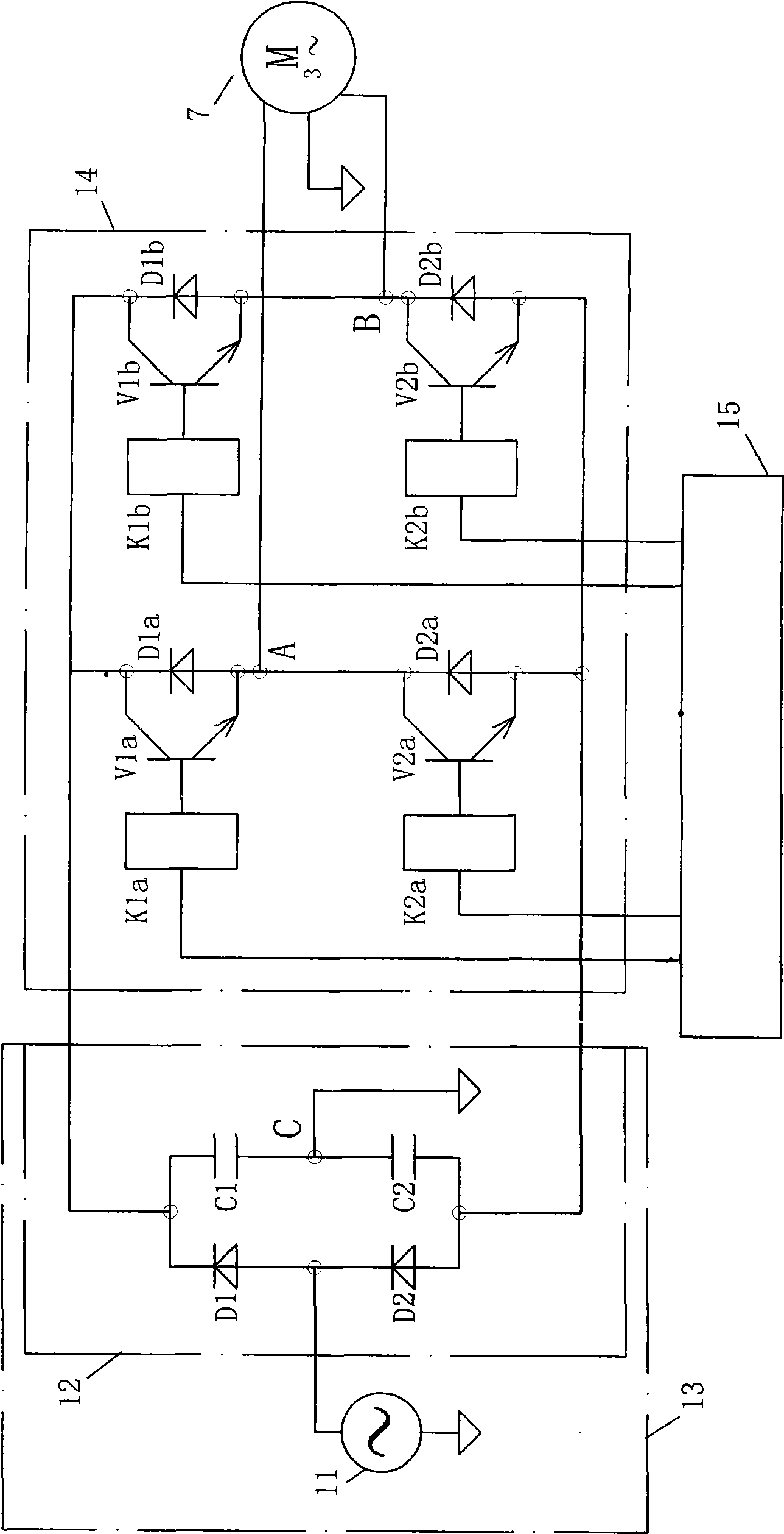
[0012] The frequency conversion drive system of the embodiment of the present invention is as figure 1 As shown, it is mainly composed of a motor 7 and a control device 10 .

[0013] The control device 10 includes: a DC power supply 13 composed of an AC power supply 11 such as 220V50HZ from the power grid, and a rectifying and filtering circuit 12 that is connected to its output and rectifies the AC power supply 11 and converts it into a DC voltage; at the output of the DC power supply terminal connected inverter circuit 14. The motor 7 is connected to an output terminal of the inverter circuit 14 . In addition, the inverter circuit 14 is connected to and controlled by the control mechanism 15 . This is a typical AC-DC-AC indirect conversion control device, but it is not limited to this, and may be an AC-AC direct conversion control device without a rectification filter circuit.

[0014] The rectifying and filtering circuit 12 includes: a rectifying and filtering circuit fo...


PUM

PropertyMeasurementUnit
The inside diameter ofaaaaaaaaaa

Abstract

The invention relates to a variable frequency driving system, where the power supply of a power grid is converted into the variable frequency power supply so as to drive a three-phase motor; the converted variable frequency power supply is a two-phase power supply which has a public end, time lag of 1 / 6 period and the same amplitudes; the two-phase power supply is connected with a three-phase terminal of the three-phase motor in the following way: the public end is connected with a phase terminal and two output terminals of the two-phase power supply are connected with another two phase terminals of the motor; and the three-phase motor has such three-phase impedance: the two-phase impedance of the two output terminals which are connected with the two-phase power supply is equal and higher than the one-phase impedance which is connected with the public end. The impedance of the two output terminals of the two-phase power supply which is connected with motor is as 1.5 times to 4.5 times as the one-phase impedance which is connected with the public end. The design can achieve the effect of improving the asymmetry of the system, thus improving the efficiency and reducing the noise of the vibration.

Description

technical field [0001] The invention relates to a variable frequency drive system and its motor. In the International Patent Classification Table, the functional classification can belong to H02P7 / 00. Background technique [0002] The three-phase inverter drive three-phase motor system has been widely used in industrial equipment, but it is used for electric appliances powered by single-phase power supply with relatively small power. The inverter circuit appears to have too many units and insufficient component capacity. Complicated circuits have also become the weak link of the system. Usually, it is necessary to select better unit components or set up more complex protection circuits and control programs, and even use relatively expensive intelligent power modules (IPM) and 16-bit single-chip microcomputers, etc., which obviously affect the cost. . For this reason, the designer of the present invention proposes to drive a two-phase motor or a three-phase motor with a two-...

Claims


Application Information

Patent Timeline
IPC IPC(8): H02P27/06H02K1/16H02K3/28H02K15/02
Inventor 区长钊镡丹中
Owner 江门金羚电机有限公司
Features
  • R&D
  • Intellectual Property
  • Life Sciences
  • Materials
  • Tech Scout
  • Unparalleled Data Quality
  • Higher Quality Content
  • 60% Fewer Hallucinations
Learn More