Injection-moulding machine with torpedo plunger plastification

A technology of injection molding machine and plunger, applied in the field of plasticizing unit, can solve the problem of inability to realize accurate measurement of plastic amount and so on

Inactive Publication Date: 2009-08-19
扎菲尔塑料机械有限责任公司
View PDF0 Cites 5 Cited by
  • Summary
  • Abstract
  • Description
  • Claims
  • Application Information

AI Technical Summary

Problems solved by technology

Precise metering of the plastic quantity is not possible for the injec

Method used


Image

  • Injection-moulding machine with torpedo plunger plastification
  • Injection-moulding machine with torpedo plunger plastification
  • Injection-moulding machine with torpedo plunger plastification

Examples


Embodiment Construction

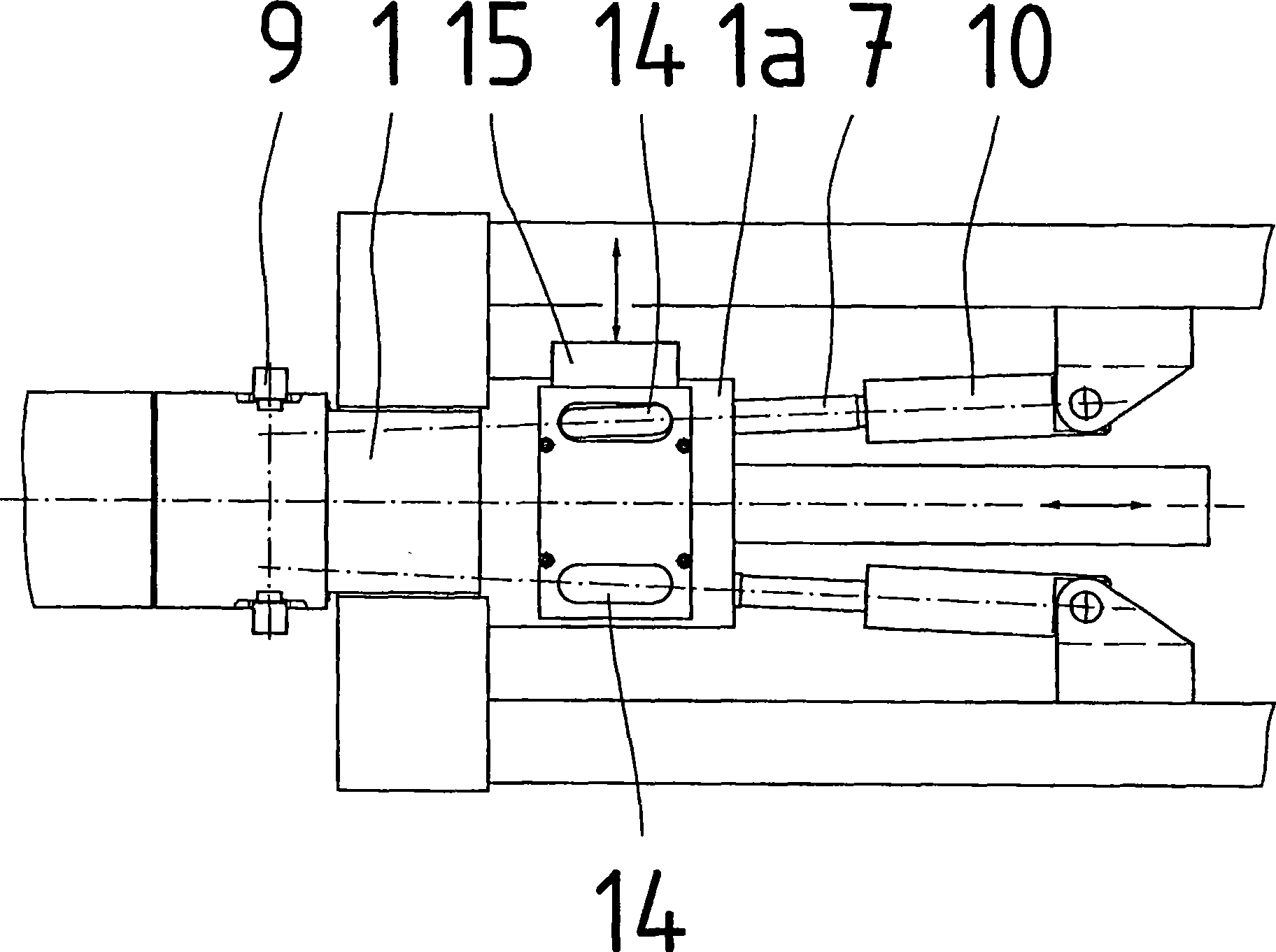
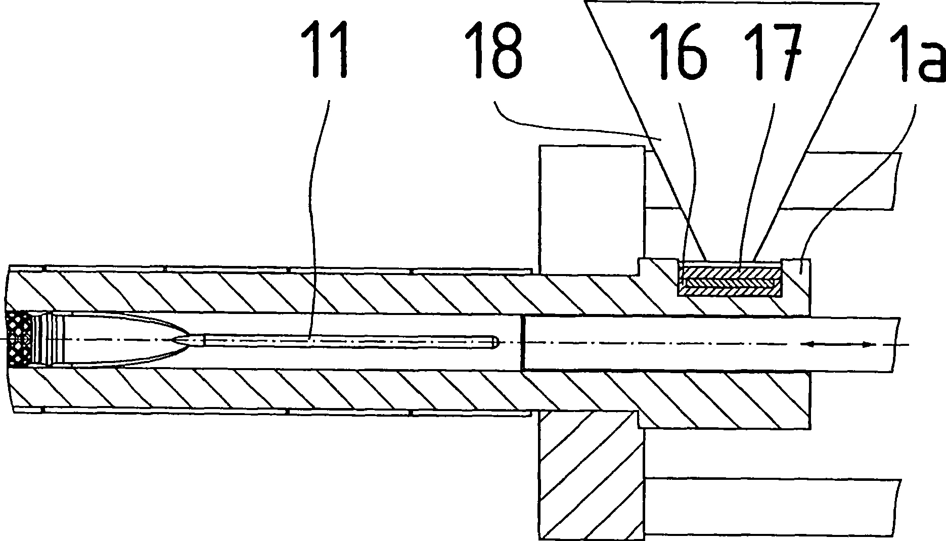
[0016] figure 1 The injection unit shown in shows a cylinder 1 with a cylinder head 2 and a nozzle 3 in which a torpedo-shaped plunger 4 connected to an injection cylinder 5 is arranged. The cylinder 1 is mounted in a housing 6 , wherein the annular surface of the cylindrically thickened cylinder end 1 a introduces the injection force into the housing 6 . In this cylinder end 1a, two smaller-diameter holes are provided on both sides next to the hole for the torpedo-shaped plunger, in which holes the filling plunger 7 is guided. These bores continue as filling channels 8 into filling channel valves 9 . What is important here is that the filling channel valve 9 alternately opens the filling channel 8 of the filling plunger 7 driven by the cylinder 10 in the direction of the nozzle, releases the connection with the filling groove 11 in the rod 4 a of the torpedo-shaped plunger 4 and Close the filling channel 8 located on the opposite side. This is a prerequisite for the situat...


PUM


Abstract

Plastification unit for an injection unit of an injection-moulding machine with a heated cylinder (1), at the front end of which a cylinder head (2) with a nozzle (3) has been secured, mounted in a housing (6), which has connection to an injection cylinder (5) and to a non-return valve (13), which inhibits the reverse flow of the plastic during injection, characterized in that in the central bore of the cylinder (1) an axially displaceable torpedo plunger (4) has been arranged which is composed of a shaft (4a) and of a combination of shear components (4b) and mixer components (4c) and which is surrounded by a stream of plastic that melted and homogenized in the process, where two feed plungers (7) operating in opposite directions have been arranged in bores laterally alongside the central bore and bring about conveying of the plastic through the feed channels (8), through the feed-channel valves (9), and through the feed grooves (11) in the shaft (4a) of the torpedo plunger (4).

Description

technical field [0001] The invention relates to a plasticizing unit of an injection molding machine for melting and conveying plastic materials, comprising a cylinder and a torpedo-shaped plunger, on the front end of which torpedo-shaped plunger is provided a backflow blocking device, wherein , the conveyance of the plastic is ensured by two opposing filling plungers on the left and right on the rear end of the cylinder next to the torpedo-shaped plunger in a divided feeding The underside of the rod works and the filling plungers are each driven by a working cylinder, wherein a slide correspondingly closes the part of the feed rod above the filling plunger that is being filled and moves in the direction of the nozzle, and a filling channel valve opens Relevant filling channels, wherein these filling channels each continue in the form of a longitudinal groove in the shaft of the torpedo plunger and open into the shearing and mixing element arranged behind the torpedo plunger, w...

Claims


Application Information

Patent Timeline
IPC IPC(8): B29C45/53B29C45/58B29C45/18
CPCB29C45/18B29C45/581B29C45/53
Inventor V·弗里茨拉
Owner 扎菲尔塑料机械有限责任公司
Why Eureka
Try Eureka