Bottle container

A container and container body technology, applied in the field of bottle containers, can solve problems such as residue, sealing material falling, and no special action, etc., to achieve the effect of improving the certainty and reducing the force

Active Publication Date: 2009-08-19
FUAN KERU
View PDF5 Cites 5 Cited by
  • Summary
  • Abstract
  • Description
  • Claims
  • Application Information

AI Technical Summary

Problems solved by technology

[0003] These known examples do not have special considerations regarding broken closure material falling into the container or remaining after cutting.

Method used


Image

  • Bottle container
  • Bottle container
  • Bottle container

Examples


Embodiment 1

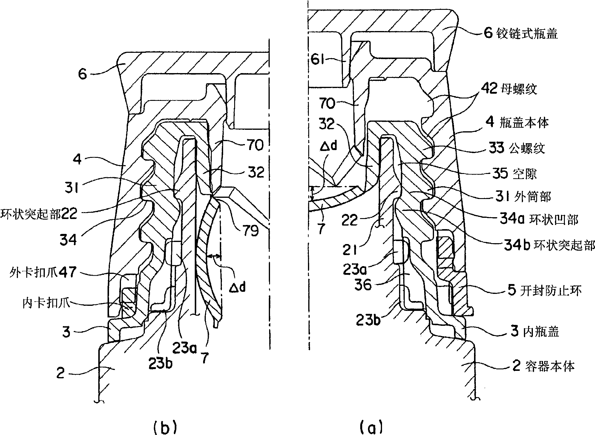
[0145] figure 1 It is a partial enlarged view showing the bottle cap of Example 1 of the present invention installed in the container body, (a) is the unused state, and (b) is the state of the unsealed sealing film.

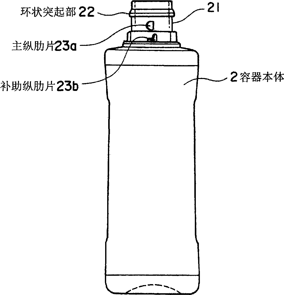
[0146] figure 2 It is an external view showing the container body.

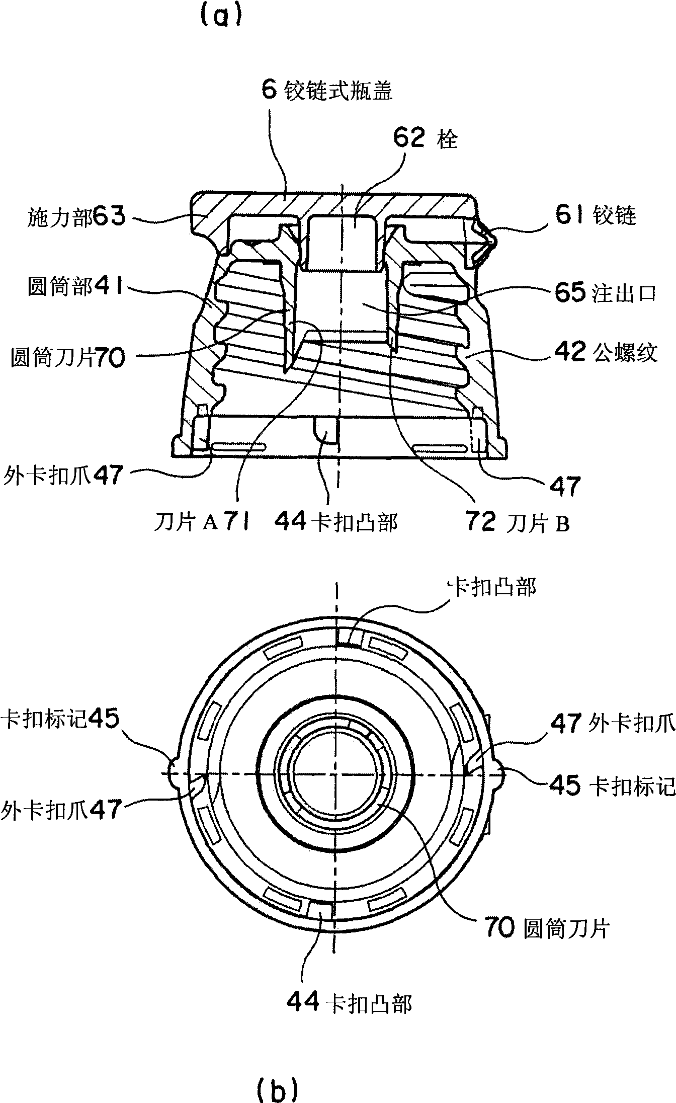
[0147] image 3 (a) is a sectional view of the bottle cap body with a hinge, (b) is a bottom view, Figure 4 (a) is an external view of the hinged cap body, and (b) is a cross-sectional view of the hinged cap body in an open state.

[0148] Figure 5 (a) is a plan view, (b) is a sectional view, (c) is a bottom view, and (d) is an external view of the inner bottle cap.

[0149] Figure 6 It is a schematic diagram showing a part of the broken surface of the anti-opening ring.

[0150] Figure 7 It is a schematic diagram of the buckle relationship of the present invention, (a) is a diagram of the completion of the buckle installation, and (b) is a state where the bottle cap body is halfwa...

Embodiment 2

[0201] Please refer to Figure 11 , Figure 12 Example 2 will be described. Parts not mentioned are in principle common to Embodiment 1.

[0202] Figure 11 It is a partial enlarged view showing the state of the bottle cap of Example 2 mounted on the container body. (a) shows the unused state, and (b) shows the state of the unsealed film. Figure 12 yes Figure 11 A cross-sectional view of each component is shown. (a) is a sectional view of the container neck, (b) is a sectional view of the inner cap, (c) is a sectional view of the cap body, and the right half (c1) shows the state where the anti-opening ring is inserted.

[0203] The biggest difference between embodiment 2 and embodiment 1 is that the upper side of the annular recess 34a of the inner bottle cap is also provided with an upper annular protrusion 34c as an annular protrusion, forming a container body together with the annular recess 34a The ring-shaped protruding portion 22 snap-fit ​​structure provided on...


PUM


Abstract

A bottle container in which an inner cap is in direct contact with a container body and a cap body is fitted by means of a screw-thread to the inner cap. A joint mechanism between the inner cap and a container body neck (21) is constructed such that projecting annular members in the horizontal direction are arranged in a top-bottom relationship to prevent them from separating from each other and that vertical ribs (23, 36) arranged on them are engaged with each other to prevent them from rotating relative to each other. Even if the cap is strongly reversely rotated in the direction of loosening the screw-thread engagement, the cap body is prevented from separating from the inner cap.

Description

technical field [0001] The present invention relates to a bottle cap provided with unsealing means. Background technique [0002] On the market, many containers with such structures have been designed and proposed regarding the structure of bottle caps used to keep the spout hole in a sealed state when not in use, and to unseal the sealing material provided on the spout hole at the beginning of use. At the same time, in order to prevent inadvertent opening when not in use, there are many bottle cap structures with mechanisms to prevent improper opening. There are also proposals for designing containers with such a structure, such as bottle caps with hinges that are used for opening and closing the caps. For example, there are Patent Document 1 (JP-A-2001-19019), Patent Document 2 (JP-A-11-349025), Patent Document 3 (Patent No. 3024089), and Patent Document 4 (JP-A-2000-247351). Bulletin), etc. [0003] In these known examples, there is nothing special about the considerat...

Claims


Application Information

Patent Timeline
IPC IPC(8): B65D51/22B65D47/08B65D47/36
CPCB65D2255/20B65D2251/0093B65D51/225B65D2251/0087B65D2251/0025B65D47/36B65D51/18B65D51/20B65D51/22
Inventor 铃木康之
Owner FUAN KERU
Why Eureka
Try Eureka