Control method

A wind wheel and generator technology, applied in engine control, engine control parameters, wind engine control, etc., can solve the problems of overrunning of bearing balls, high time and cost, and reduced lubrication, etc., to achieve time period extension, Effect of low cost and loss reduction

Inactive Publication Date: 2009-08-19
ABB RES LTD
View PDF0 Cites 14 Cited by
  • Summary
  • Abstract
  • Description
  • Claims
  • Application Information

AI Technical Summary

Problems solved by technology

One reason for this is that the lubrication of the different components is reduced under these conditions, since no safe film of lubricant / grease is formed on the bearings
Also, under these conditions, dents can damage surfaces that are normally lubricated under normal power conditions and periodically cause bearing balls to overrun
Especially for offshore wind farms this could be devastating as the time and cost required to repair the gearbox and / or bearings would be considerable

Method used


Image

  • Control method
  • Control method
  • Control method

Examples


Embodiment Construction

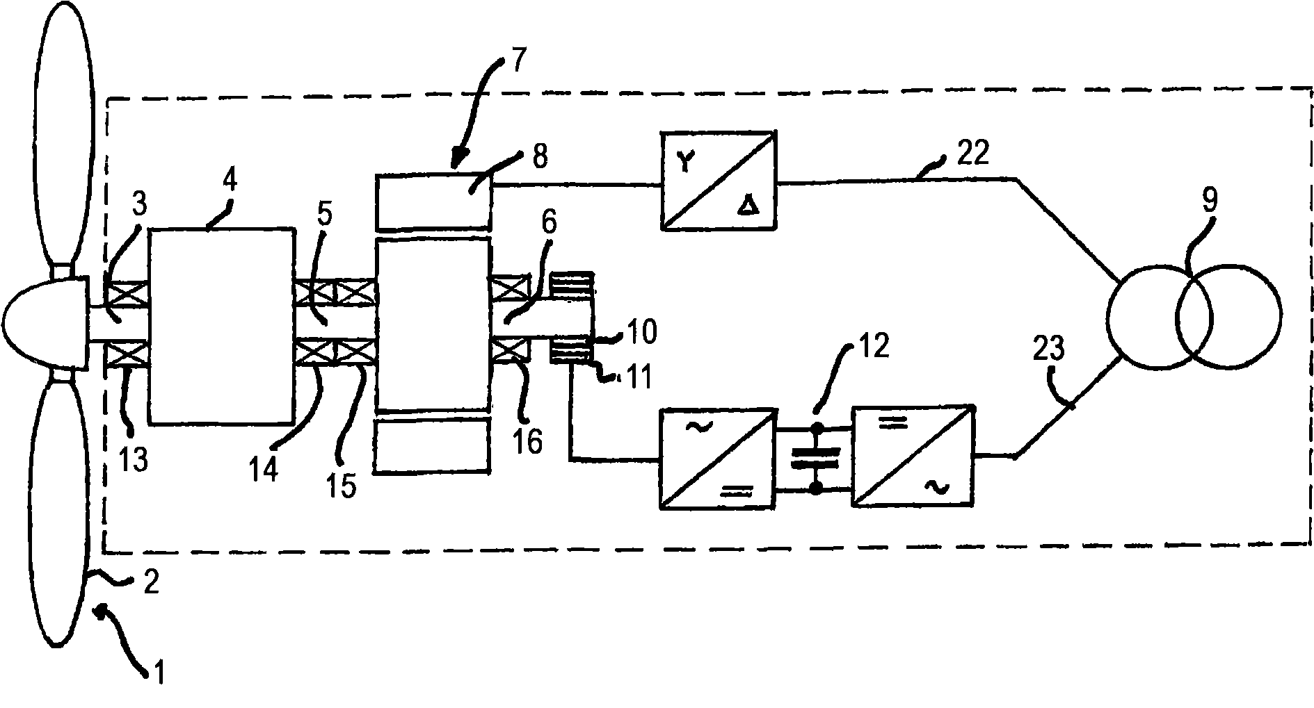
[0024] figure 1 The general structure of a wind turbine, known as a wind turbine with a double-fed induction generator (DFIG), is illustrated very schematically. The components of the wind turbine within the dashed box are usually arranged in a so-called nacelle or casing, which is arranged on the column of the wind power plant. The wind turbine has a propeller 1 with blades 2 arranged to capture the wind and drive a rotor 3 in rotation. For wind turbines rated at 3MW and 2MW, the rotor typically has rotational speeds of 3-15 rpm and 5-20 rpm, respectively. The rotor 3 is connected to a gearbox 4, which normally increases the rotational speed on its output shaft 5 to 100 times the rotational speed of the rotor 3 for higher ratings, and makes it output for lower ratings The rotational speed on the shaft 5 is increased to 60 times the rotational speed of the rotor 3 . The output shaft 5 is connected to or carries the rotor 6 of an asynchronous generator 7 having stator windin...


PUM


Abstract

A generator (7) of a wind turbine is at low power conditions operated as a motor by control of a frequency converter (12) to feed electric power from an electric power transmission network to the generator for raising the speed of the wind rotor above a predetermined level for lubricating rotating parts of a drive train of the wind turbine.

Description

technical field [0001] The present invention relates to a wind turbine comprising a drive system having a rotor connected to a rotor of a generator through a gearbox and having bearings for journaling the rotating parts of the drive system, the generator being adapted to connected to the electricity grid. Background technique [0002] Thus, in this disclosure, a "wind turbine" is defined to include a rotor with turbine blades, a gearbox, a generator and associated equipment, and a transformer for feeding from the generator to or connected to the transmission network Electric device. [0003] The generator in the wind turbine may be of any known type, such as an asynchronous generator with a stator winding adapted to be connected to the transmission network and a rotor connected to a frequency converter via slip rings and brushes, with a squirrel cage Asynchronous generator with wound rotor, or a synchronous generator. [0004] For wind turbines, low power conditions, mean...

Claims


Application Information

Patent Timeline
Patent Type & Authority Applications(China)
IPC IPC(8): F03D7/02
CPCF05B2270/1095Y02E10/723Y02E10/725F05B2240/20F03D9/002F05B2270/101F05B2270/32F03D11/0008F05B2270/327F03D7/00Y02E10/722Y02E10/72F03D7/026F03D9/25F03D80/70
Inventor L·格特玛L-E·雷伊H·C·克里斯坦森J·曼特尔E·科尔比·尼尔森
Owner ABB RES LTD
Why Eureka
Try Eureka