Transmission device

A technology of transmission device and transmission gear, which is applied in the direction of hoisting device, portable lifting device, components with teeth, etc., and can solve the problems of high mechanical load of parts bearings

Inactive Publication Date: 2009-08-19
ROBERT BOSCH GMBH
View PDF2 Cites 3 Cited by
  • Summary
  • Abstract
  • Description
  • Claims
  • Application Information

AI Technical Summary

Problems solved by technology

As a result, the two transmission gears are pressed apart, which places a high mechanical load on the components, especially on the bearings

Method used


Image

  • Transmission device
  • Transmission device
  • Transmission device

Examples


Embodiment Construction

[0023] In the drawings, the same symbols denote the same components or components having the same functions.

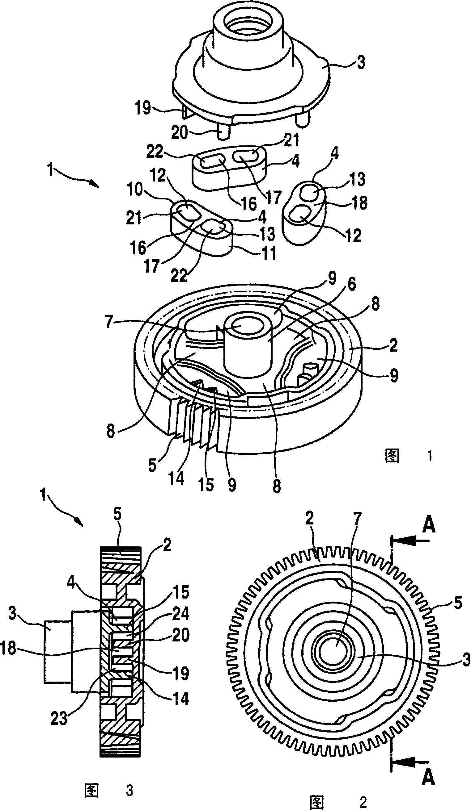
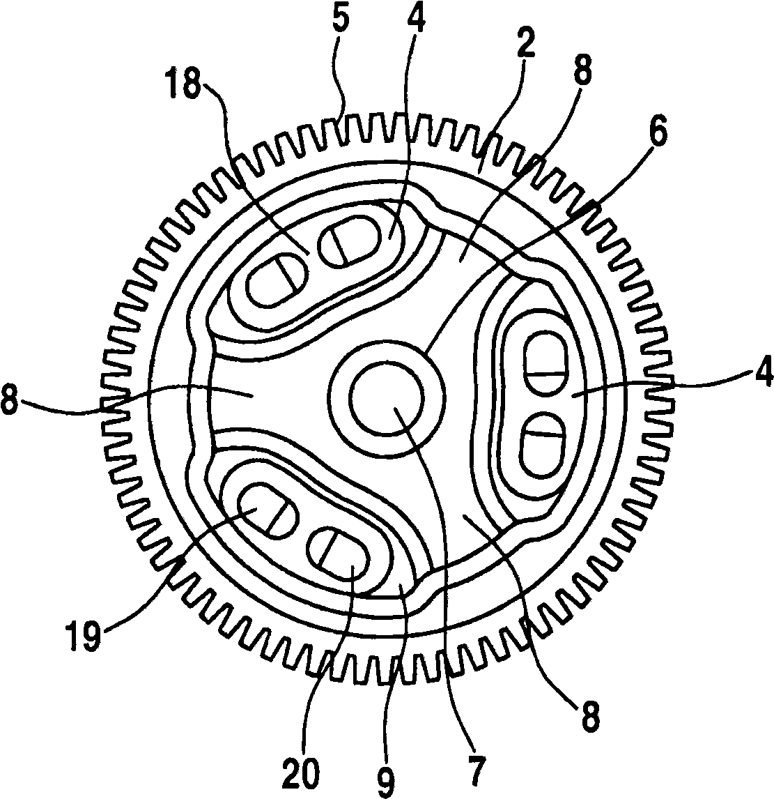
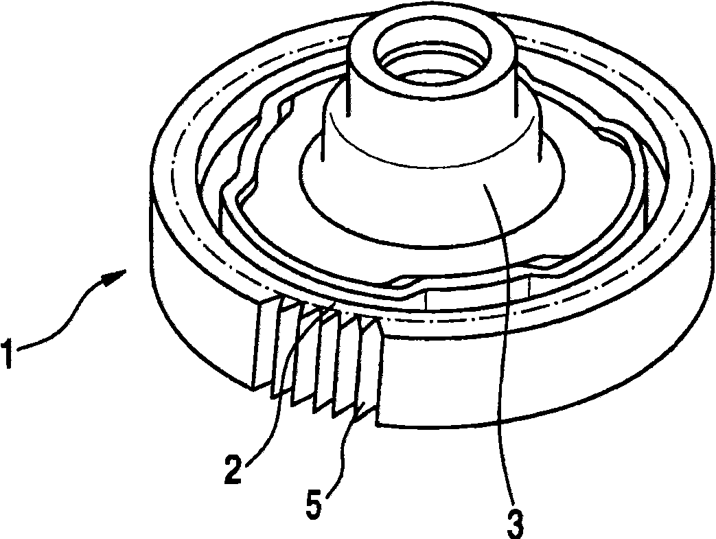
[0024] The transmission 1 shown in the drawing has a first transmission gear 2 in the form of a spur gear and an axially spaced second transmission gear 3 in the form of a driven wheel. Between the first transmission gear 2 and the second transmission gear 3, three damping elements 4 are provided which are respectively distributed staggered by 120° on the circumference. The damping element 4 is used to apply damping on the circumference and to transmit torque between the two drive gears 2 , 3 . During operation of the transmission, the damping element 4 receives only tension in the circumferential direction from the transmission gears 2 , 3 .

[0025] The first transmission gear 2 configured as a spur gear is provided with outer gear teeth 5 and with an inner hub 6 arranged coaxially therewith with a central perforation 7 for supporting the transmission 1 on a suppor...


PUM


Abstract

The invention relates to a transmission device (1) comprising a first gear wheel (2) and a second gear wheel (3) that is rotatably coupled thereto, wherein a damping element (4) acting in the circumferential direction is provided axially between the gear wheels (2, 3). According to the invention it is provided that the damping element (4) can be tensioned by the gear wheels (2, 3) during the operation of the transmission device (1).

Description

technical field [0001] The invention relates to a transmission device according to the preamble of claim 1 . Background technique [0002] Such transmissions are used in particular in motor vehicle adjustment devices, such as electric window regulators or sliding sunroofs, which are driven by means of an electric motor. In particular, electric motors are used for this purpose, which adjust the window via a drive, for example between the open and closed end positions. Because in operation, vibrations and / or undesired shock loads can occur when the motor starts up or hits the end positions, it is known to provide damping between two axially adjacent drive gears element. Such a transmission is described as state of the art in DE 102 46 711 A1. In the known transmission, the force is transmitted from the spur gear to the driven wheel in the circumferential direction by means of a damping element. When an end position is hit or when an impact load is applied, the damping elem...

Claims


Application Information

Patent Timeline
IPC IPC(8): F16H55/14
CPCF16H55/14Y10T74/19633Y10T74/19898Y10T74/19623
Inventor F·塔什W·豪塞克H·索恩V·赫特韦克P·博尔M·菲德勒D·德普纳
Owner ROBERT BOSCH GMBH
Why Eureka
Try Eureka