Saddle type penis holder

A support, saddle-shaped technology, applied in non-surgical orthopedic surgery and other directions, can solve the problems of high technical difficulty, low one-time success rate of welding process, and unsatisfactory anti-torsion ability of connection breakpoints.

Inactive Publication Date: 2009-08-26
易明光
View PDF2 Cites 4 Cited by
  • Summary
  • Abstract
  • Description
  • Claims
  • Application Information

AI Technical Summary

Problems solved by technology

However, in this solution, the twisting resistance of the connecting breakpoint is still not ideal, although no twisting force will appear in normal use
In addition, the connection process at the bre

Method used


Image

  • Saddle type penis holder
  • Saddle type penis holder
  • Saddle type penis holder

Examples


Embodiment Construction

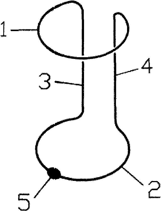
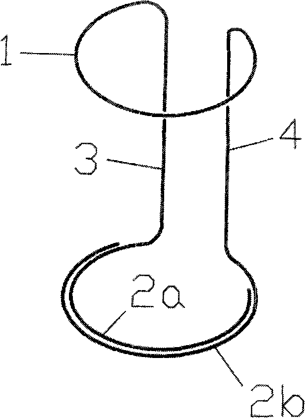
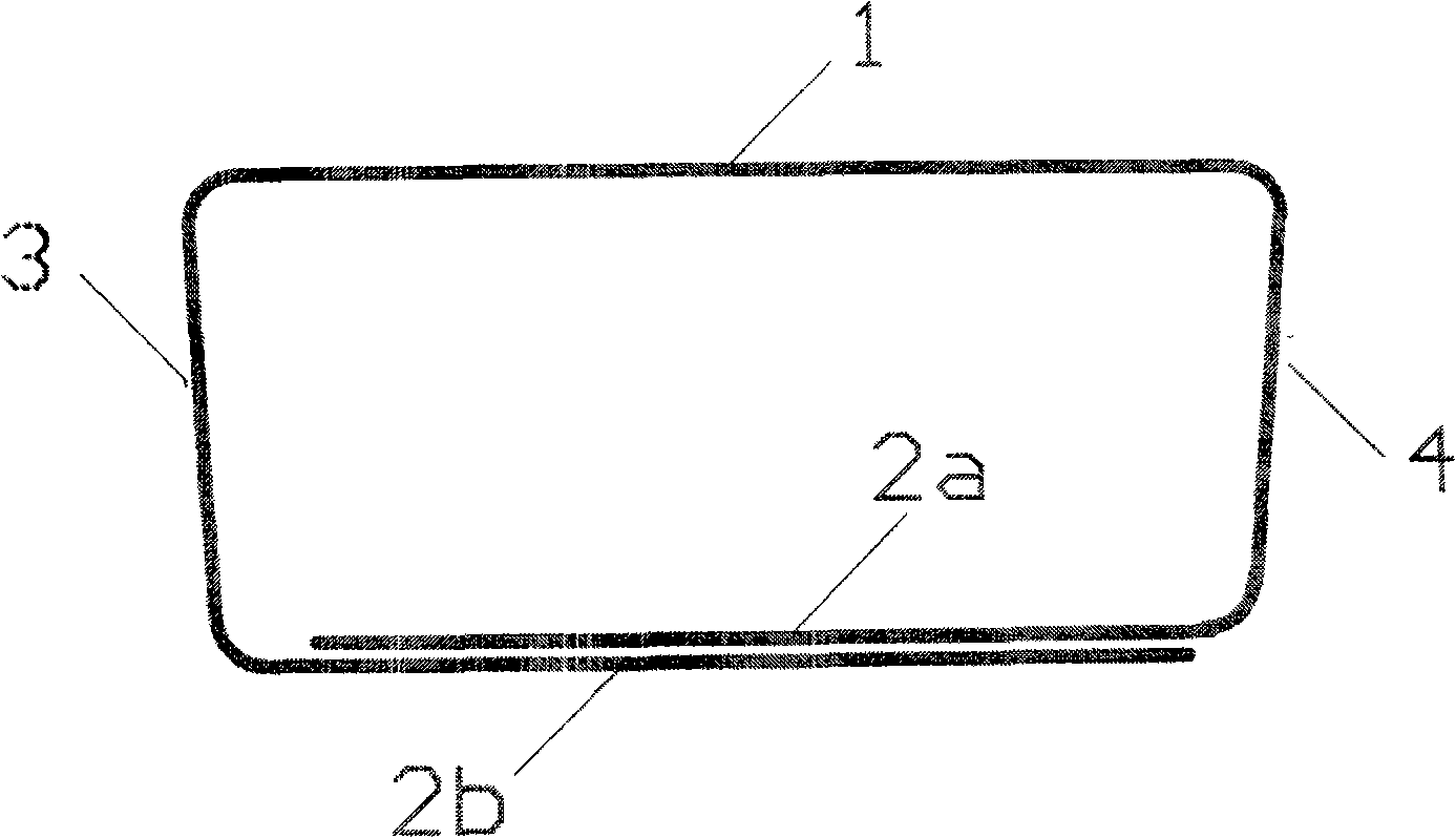
[0017] Embodiments of the saddle penis support of the present invention, such as Figure 2 As shown, at first a saddle-shaped frame with two sub-rings 2a and 2b is formed with wire rod. The frame wire can use memory alloy, or other high-strength, high-elasticity materials. Such as Figure 2 After the saddle-shaped frame shown is formed, the two sub-rings 2a and 2b are combined and put on with collars 6,7. Collars 6, 7 also adopt high-strength metal materials. Collar position as Figure 4 As shown, expand the two ends of the diagram in the lower ring. After the collar and the lower ring are positioned, use resin or superglue to fill the gap in the collar.

[0018] For such as Figure 6 The situation shown is also shaped first as Figure 2 The frame with complete sub-lower rings 2a and 2b is shown, and then the sub-lower rings 2a and 2b are cut off at appropriate positions, and then the binding collar 5 is put on the partial overlapping area of ​​the sub-lower rings 2a an...


PUM


Abstract

Disclosed is a saddle type penis holder to hold the penis for the impotence patient, maintain and increase the erection rigidity and improve the sexual potency of the patient. The saddle type penis holder is formed by a single metal wire, comprises an upper ring (1), a lower ring and two holding levers (3) and (4), and is characterized in that: the lower ring is a compound ring which is forming by the overlapping of two lower subrings (2a) and (2b). In addition, the compound ring is bound and fixed by two sleeve rings (6) and (7). The holder with the structure has better break resistance strength and racking resistance capability.

Description

technical field [0001] The invention relates to a saddle-shaped penis supporter, which is used for helping impotence patients to support the penis, maintaining and enhancing erection rigidity, and helping the patients to improve and resume sexual intercourse. Background technique [0002] Saddle-shaped topology is the most ideal configuration for external support devices for impotence treatment. The recent patent "penis support", publication number: CN1853585A (Yi Mingguang) proposes a realizable structure of saddle topology. The structure is formed from a single wire with only one closed connection break, as in Figure 1 Show. Its follow-up improvement patent ZL200620120018.6 (Yi Mingguang) also proposed an improvement plan for the fracture resistance of the connection breakpoint. This is an almost perfect result. However, in this solution, the twisting resistance of the connection breakpoint is still not ideal, although no twisting force will appear in normal use. In a...

Claims


Application Information

Patent Timeline
IPC IPC(8): A61F5/41
Inventor 易明光
Owner 易明光
Why Eureka
Try Eureka