Unlock instant, AI-driven research and patent intelligence for your innovation.

Transmission apparatus and computer program

A technology of transmission device and transmission volume, which is applied in the direction of measuring device, transportation packaging, transportation and packaging, etc., which can solve the problems of inability to eliminate transmission offset, calculation of correction amount, uneven transmission volume, etc., so as to suppress measurement errors and suppress Influence of measurement error, effect of high transmission accuracy

Active Publication Date: 2009-08-26
MURATA MFG CO LTD
View PDF1 Cites 2 Cited by
  • Summary
  • Abstract
  • Description
  • Claims
  • Application Information

AI Technical Summary

Problems solved by technology

In this case, although it is possible to cope with a large deviation in the conveying amount such as periodic feed unevenness caused by the eccentricity of the roller itself, it cannot Calculate the appropriate correction amount
[0008] In addition, for example, when the material of the conveyor belt, sheet, etc. is a material that is easy to expand and contract due to changes in temperature and humidity, such as paper and synthetic resin, the entire length of the conveyor belt, sheet, etc. will expand and contract, even if the previous Offset corrects teleport amount, does not remove teleport offset overall

Method used


Image

  • Transmission apparatus and computer program
  • Transmission apparatus and computer program
  • Transmission apparatus and computer program

Examples


Embodiment approach 1

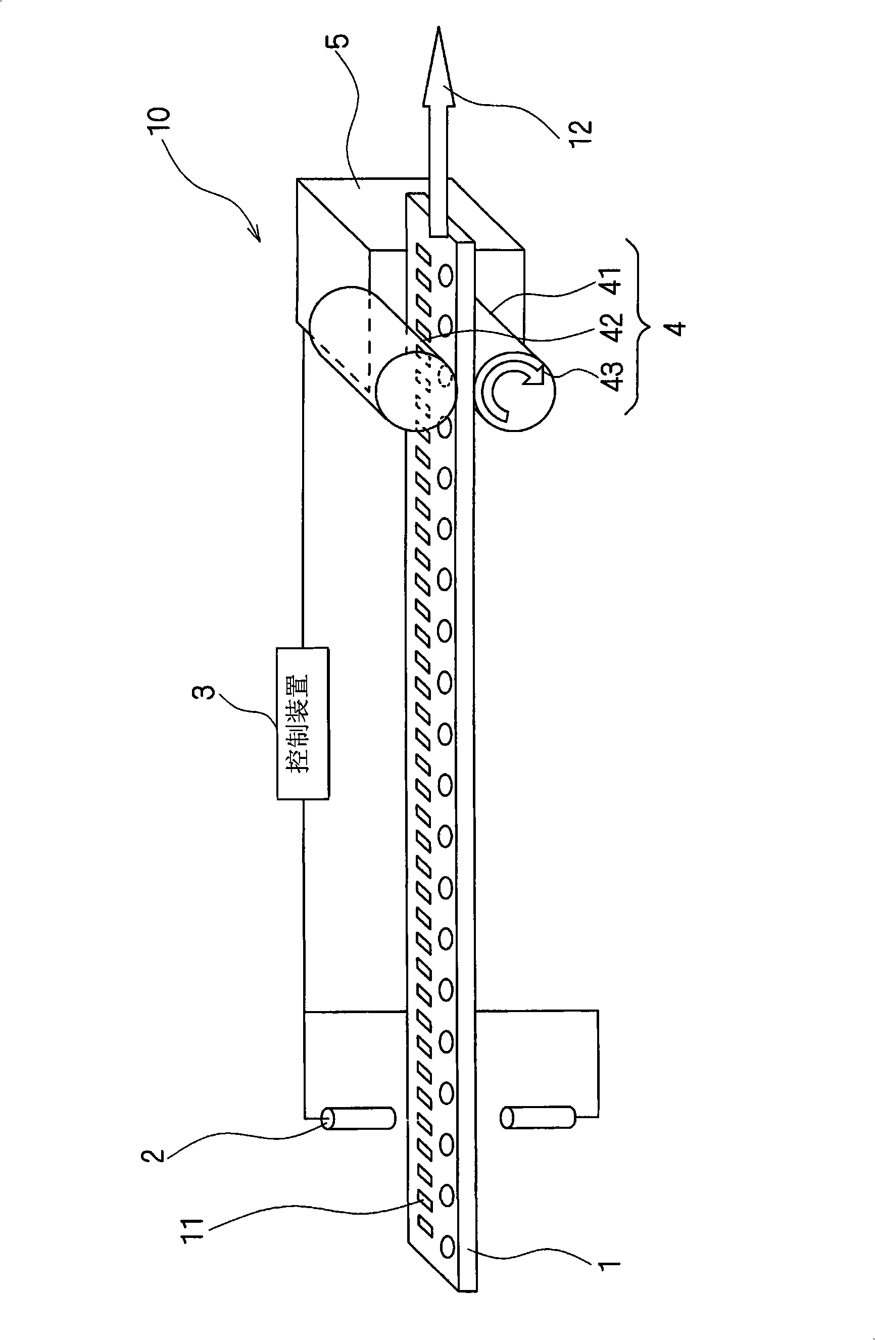
[0060] figure 1 It is a perspective view schematically showing the configuration of the transmission device according to Embodiment 1 of the present invention. Such as figure 1 As shown, the conveying device 10 related to the first embodiment can use the conveying roller 4 to convey the belt-shaped continuum, that is, the conveyer belt 1. On the belt-shaped continuum, recesses 11, 11, ... are formed at substantially equal intervals for As a mark when delivering electronic parts.

[0061] The conveyance roller 4 is composed of a feed roller 41 connected to a drive source 5 such as a motor, and a pressure roller 42 that pinches the conveyance belt 1 . The conveyor belt 1 is pinched between the feed roller 41 and the pressure roller 42 , and the feed roller 41 rotates in the direction indicated by the arrow 43 to transport the conveyor belt 1 in the direction indicated by the arrow 12 .

[0062] exist figure 1 Near the center of the conveyor belt 1, the electronic components ...

Embodiment approach 2

[0089] Since the configuration of the transmission device 10 according to the second embodiment of the present invention is the same as that of the first embodiment, the same reference numerals are assigned to the same components and their descriptions are omitted. The second embodiment differs from the first embodiment in that the rotary encoder 20 for detecting the rotation angle of the conveyance roller 4 is provided, and the feed amount is corrected using the stop position estimated from the rotation angle of the drive source 5 .

[0090] Figure 8 It is a perspective view schematically showing the configuration of the transmission device according to Embodiment 2 of the present invention. Such as Figure 8 As shown, the conveying device 10 related to the second embodiment can convey the conveying belt 1 on the conveying roller 4, and recesses 11, 11, ... are formed on the conveying belt 1 at approximately equal intervals, which are used as marks when conveying electronic...


PUM


Abstract

The invention provides a conveyance apparatus and a computer program capable of effectively correcting offset of either periodic feeding unequal conveying capacity or burst conveying capacity, and precisely implementing conveyance of a continuous body such as a belt, a sheet or the like. The conveyance apparatus comprises a pair of upper and lower conveyance rollers for conveying belt shaped continuous articles, a driving motor for driving the rollers, and a sensor for detecting the mark of continuous articles. Whether the mark is detected by the sensor is determined when the predetermined conveyance capacity is executed; an ON signal or an OFF signal is generated according to whether the mark is detected; a count value is set on the basis of generated ON signal or OFF signal, and stored; and the conveyance capacity of the belt shaped continuous body is corrected on the basis of a stochastic value of a plurality of count values and the count value set at the previous time point.

Description

technical field [0001] The present invention relates to a conveying device and a computer program capable of stably conveying a belt-shaped continuum such as a conveyor belt. Background technique [0002] In the past, there has been widely provided a conveying device that winds long materials such as films and tapes, strip-shaped materials, etc. wound on a feed roller onto a take-up roller equipped with a rotary drive, thereby conveying long lengths. Dimensional material, strip material, etc. Using this kind of conveying device, for example, in the course of the manufacturing process, the rotary drive is temporarily stopped intermittently, during the stop period, the specified part of the long material, strip material, etc. On the roll for winding, the desired product is manufactured in this way. [0003] In recent years, the demand for small components such as LSIs, ultra-small capacitors, and ultra-small inductors has increased rapidly due to the thinner, thinner (miniat...

Claims


Application Information

Patent Timeline
IPC IPC(8): B65H20/02B65B41/16B65B15/04G01B21/06G05D3/12
Inventor 富冈弘嗣小林健一
Owner MURATA MFG CO LTD
Features
  • R&D
  • Intellectual Property
  • Life Sciences
  • Materials
  • Tech Scout
  • Unparalleled Data Quality
  • Higher Quality Content
  • 60% Fewer Hallucinations
Learn More