

Starter solenoid switch with improved arrangement of resistor
A technology of electromagnetic switch and resistance, which is used in the starting of the engine, the starting of the motor for the engine, the electromagnetic relay, etc., can solve the problems of increasing the weight of the electromagnetic coil and the electromagnetic switch.
- Summary
- Abstract
- Description
- Claims
- Application Information
AI Technical Summary
Problems solved by technology
Method used
Image


Examples
no. 1 approach
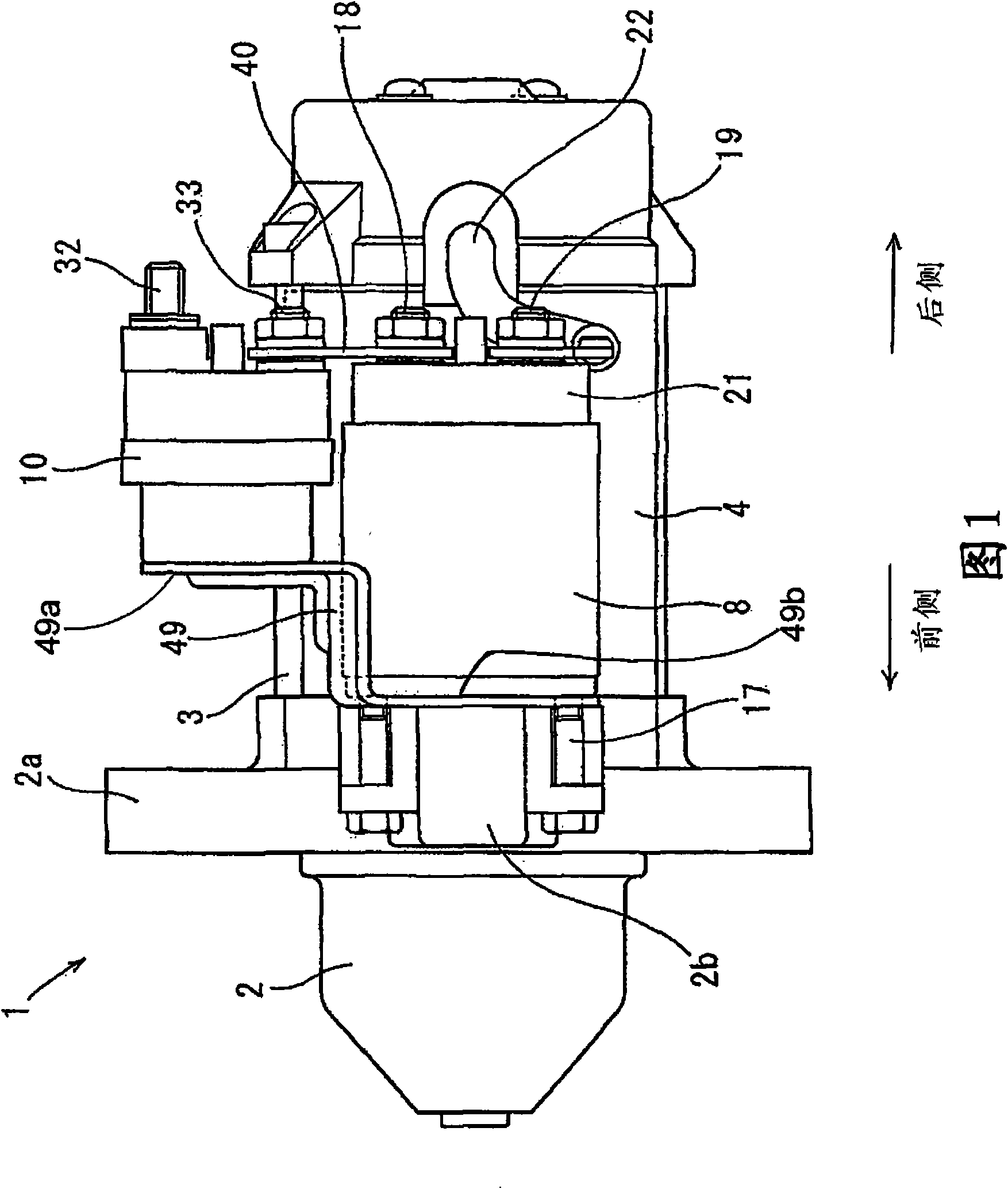
[0034] figure 1 The overall structure of a starter 1 for starting an internal combustion engine of a motor vehicle is shown, which includes a solenoid switch 10 according to a first embodiment of the invention. figure 2 The electrical circuit of the starter 1 is shown.
[0035] The starter 1 includes: a housing 2 mounted on an engine (not shown), a motor 4 fixed to the housing 2 by a plurality of through bolts 3, a ring gear 5 configured to communicate with the engine (see figure 2 ) in order to transmit the torque generated by the motor 4 to the pinion 6 of the engine (see figure 2 ), a lever 7 configured to move the pinion 6 in the axial direction of the starter 1 to engage or disengage the pinion 6 with the ring gear 5 (see figure 2 ), an electromagnetic switch 8 as a main switch of the starter 1, a resistor 9 that limits current supplied from the battery 12 to the motor 4 during a starting operation, and an electromagnetic switch 10 as a sub switch of the starter 1 a...
no. 2 approach
[0091] This embodiment describes the method of bonding the resistor 9 to the terminal bolts 32 and 33 .
[0092] refer to Image 6 , In this embodiment, the end bolt 32 has a hole 32a having a predetermined depth on its front end face. The terminal bolt 32 also has two grooves 32 b formed on the side surface of the terminal bolt 32 and facing each other in the radial direction of the terminal bolt 32 sandwiching the hole 32 a therebetween. Similarly, the terminal bolt 33 has a hole 33a of predetermined depth formed in its front end face. The terminal bolt 33 also has two grooves 33b formed on the side surface of the terminal bolt 33 and facing each other in the radial direction of the terminal bolt 33, sandwiching the hole 33a therebetween. It should be noted that in Image 6 In , the anterior direction and the posterior direction are introduced for the convenience of explanation.
[0093] The first end 9 a of the resistor 9 is inserted into the hole 32 a of the terminal b...
no. 3 approach
[0101] This embodiment describes another way of incorporating the resistor 9 to the terminal bolts 32 and 33 .
[0102] refer to Figure 7 , in the present embodiment, the end bolt 32 has a protrusion 32c protruding from the front end surface of the end bolt 32 and protruding from the front end surface by a predetermined height. In addition, if Figure 8 As shown, protrusion 32c has a rectangular bottom and tapers towards its top to have a trapezoidal cross-section. Similarly, the terminal bolt 33 has a protrusion 33c protruding from the front end face of the end bolt 33 by a predetermined height from the front end face. In addition, if Figure 8 As shown, protrusion 33c has a rectangular bottom and tapers towards its top to have a trapezoidal cross-section.
[0103] The first end 9a and the second end 9b of the resistor 9 are respectively arranged on the top ends of the protrusions 32c and 33c of the end bolts 32 and 33, and are respectively joined to the top ends of the ...
PUM
 Abstract
Description
Claims
Application Information