Aquatic animal air-transmission system control valve with functions of alarming and protection

A technology of gas transmission system and protection function, applied in the direction of control valve, functional valve type, valve device, etc.

Active Publication Date: 2010-10-13
DONGGUAN HENGYUE INDAL
View PDF0 Cites 0 Cited by
  • Summary
  • Abstract
  • Description
  • Claims
  • Application Information

AI Technical Summary

Problems solved by technology

However, due to the existence of a large number of floating objects in the water, these floating objects will gradually accumulate in the trachea opening, which will gradually block the trachea opening. Once the trachea opening is blocked, the air outlet of the aquarium air delivery system will be blocked, and the pressure on each component will gradually increase. Large, when the air pressure of the aquarium air delivery system exceeds a certain value due to blocked air outlet, it will damage the air pump and other components of the system

Method used


Image

  • Aquatic animal air-transmission system control valve with functions of alarming and protection
  • Aquatic animal air-transmission system control valve with functions of alarming and protection
  • Aquatic animal air-transmission system control valve with functions of alarming and protection

Examples


Embodiment 1

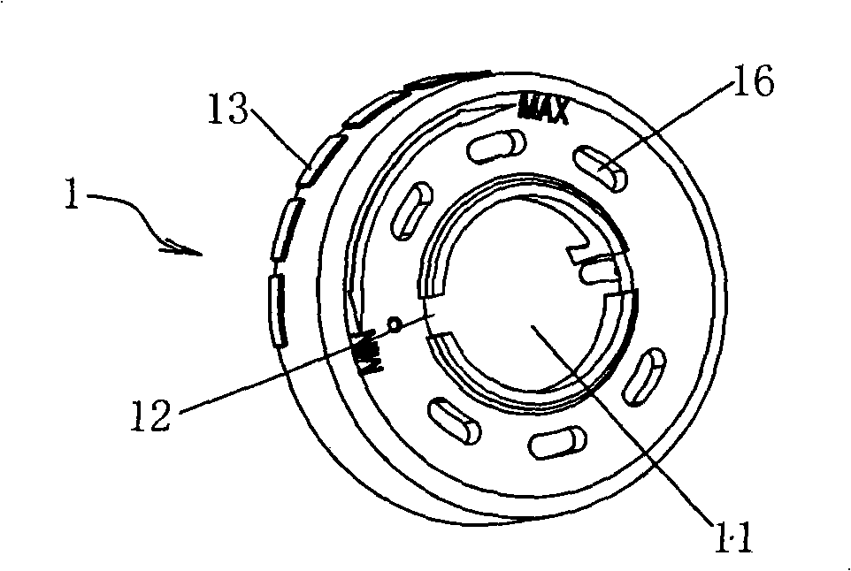
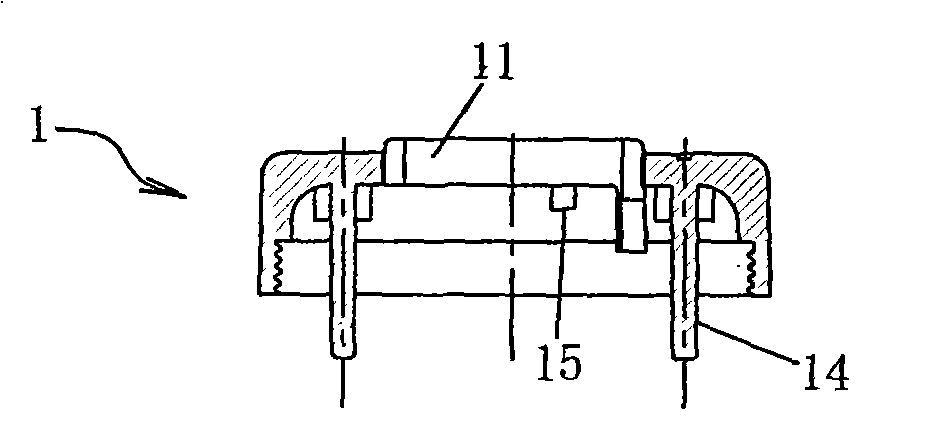
[0039] figure 1 , figure 2 , Figure 16 , Figure 18 The shown aquarium air transmission system control valve with alarm and protection functions includes an air inlet 6 and an air outlet 7, and a main valve passage 8 is provided between the air inlet 6 and the air outlet 7, and a main valve passage 8 is arranged in the main valve passage 8. There is a check valve 9, and an air chamber 4 is provided on the side of the main valve passage 8. The overall external shape of the air chamber 4 is cylindrical, and a planar circular spacer 3 is arranged between the main valve passage 8 and the air chamber 4. The circular spacer 3 forms the bottom wall of the air chamber, and the middle of the circular spacer 3 is provided with a vent hole 31, and the starting end of the vent hole 31 is Figure 19 , Figure 8 In the CD end, the end of the vent hole 31 is Figure 19 in the EF terminal, Figure 19 The vent hole 31 total area in is 15mm 2 (the total area from the end CD to the end...

Embodiment 2

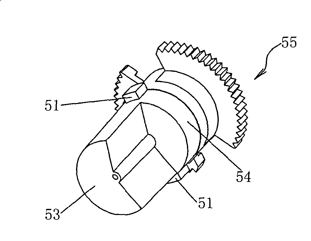
[0048] In this embodiment, in the positioning structure between the spacer and the top cover, the spacer is integrally formed with a vertical rod, the top cover is integrally formed with a hollow vertical sleeve, and the vertical rod is inserted into the vertical sleeve. In addition, in the second embodiment, the total area of ​​the vent hole 31 is 5.0mm 2 ; When the projection 51 in the middle of the adjustment knob is rotated to the position blocked by the air chamber limit block 15, the vent hole is partially covered by the lower end surface of the adjustment knob, leaving 1.0mm 2 ventilation area.

[0049] In this example, S / θ 1 / 4 =12.

[0050] All the other are the same as the first embodiment.

Embodiment 3

[0052] In this embodiment, the total area of ​​the vent hole 31 is 20mm 2 ; When the projection 51 in the middle of the adjustment knob is rotated to the position blocked by the air chamber limit block 15, the vent hole is partially covered by the lower end surface of the adjustment knob, leaving 3.0mm 2 area;

[0053] In the third embodiment, the limit stopper in the air chamber protrudes from the upper surface of the spacer. When the fan-shaped edge at the lower end of the adjustment knob touches the limit stopper, the limit stopper can prevent the adjustment knob from continuing to rotate. In the case of this design, the protrusion 51 is used as an axial positioning protrusion, and the lower end of the adjustment knob is used as a circumferential limiting protrusion due to its fan-shaped structure.

[0054] In the third embodiment, S / θ 1 / 4 = 13.5.

[0055] The rest of the structure of the third embodiment is the same as that of the first embodiment.


PUM


Abstract

An aquatic animal air-transmission system control valve with function of alarming and protection comprises an air inlet and an air outlet. A main valve channel is provided between the air inlet and the air outlet. An air chamber is provided at the side surface of main valve channel. An air discharge opening with the magnitude of 5-20mm<2> is provided between the main valve channel and the air chamber. The air chamber is provided with an air outlet communicated with the outside. The area magnitude of air discharge opening is adjustable. The aquatic animal air-transmission system control valve of the invention can send out alarming sound and automatically protects the air pump from breakage when the air pump is blocked.

Description

technical field [0001] The invention belongs to the technical field of aquarium and aquaculture equipment, and in particular relates to a control valve of an aquarium air transmission system with alarm and protection functions. Background technique [0002] In the process of aquaculture or aquaculture, it is necessary to rely on the air pump to continuously inject air or other gases into the water to ensure the normal growth of the cultured organisms. However, due to the existence of a large number of floating objects in the water, these floating objects will gradually accumulate in the trachea opening, which will gradually block the trachea opening. Once the trachea opening is blocked, the air outlet of the aquarium air delivery system will be blocked, and the pressure on each component will gradually increase. Large, when the air pressure of the aquarium air delivery system exceeds a certain value due to blocked air outlet, it will damage the air pump and other components...

Claims


Application Information

Patent Timeline
Patent Type & Authority Patents(China)
IPC IPC(8): F16K37/00F16K15/00A01K63/04
Inventor 余锋
Owner DONGGUAN HENGYUE INDAL
Why Eureka
Try Eureka