Socket for connection

A socket and connector technology, which is applied in the direction of connection, fixed connection, and components of the connection device, etc., can solve the problems of low profile and enlargement of socket 203, etc.

Inactive Publication Date: 2009-08-26
SMK CO LTD
View PDF2 Cites 4 Cited by
  • Summary
  • Abstract
  • Description
  • Claims
  • Application Information

AI Technical Summary

Problems solved by technology

Therefore, since the spring force acting as the contact pressure applied when the plug contacts 260 come into contact is the base end portion of the first spring contact piece 224 and the configuration that deforms the contact portion 228 with the point A as the starting point of U-shaped bending as a fulcrum, Therefore, increasing the thickness of the socket 203 in order to obtain the spring force at the U-shaped bending part has the problem of becoming an obstacle to lowering the profile.
[0027] In addition, since the contact portion 228 becomes a free end and moves without restriction when fitting, the contact with the contact portion 228 is good, so it has the function of contacting the plug. Point 260 is provided with a second spring contact piece 264 with a spring force, and must be formed in such a way as to obtain good contact

Method used


Image

  • Socket for connection
  • Socket for connection
  • Socket for connection

Examples


Embodiment 1

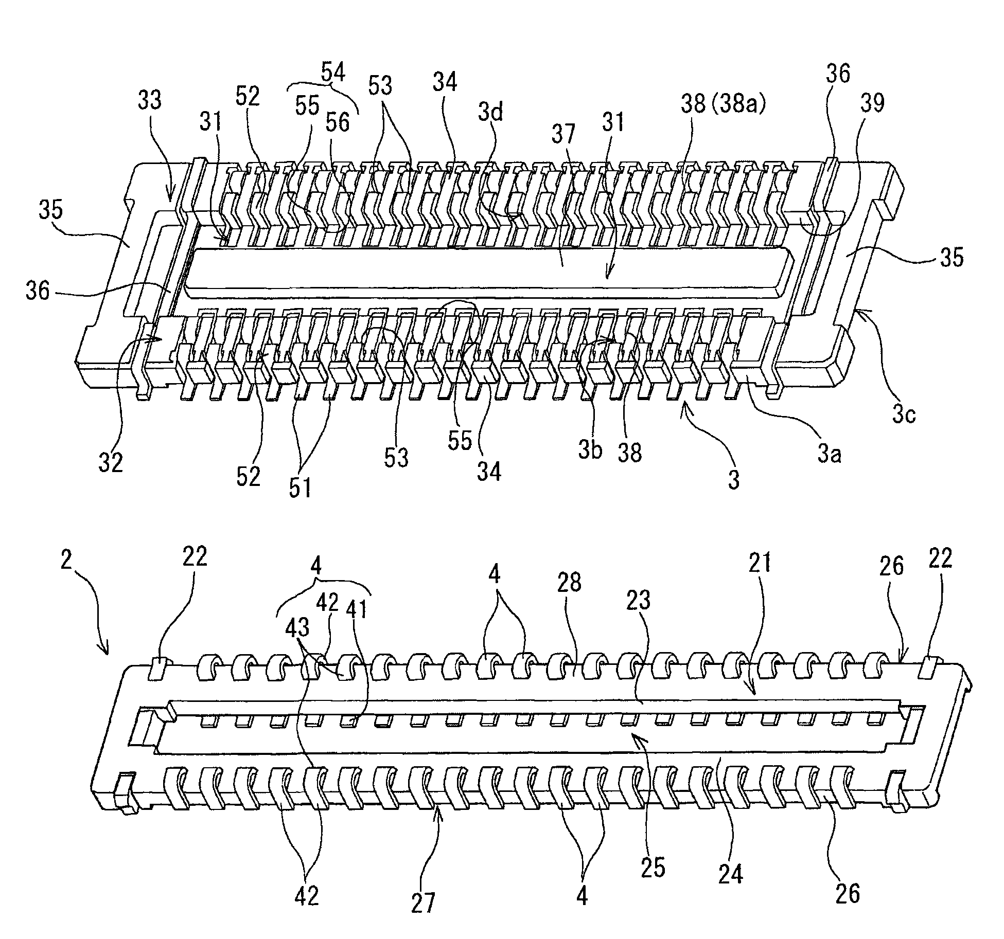
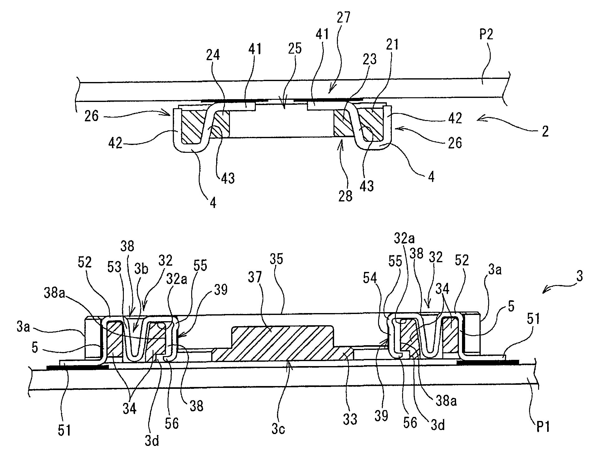
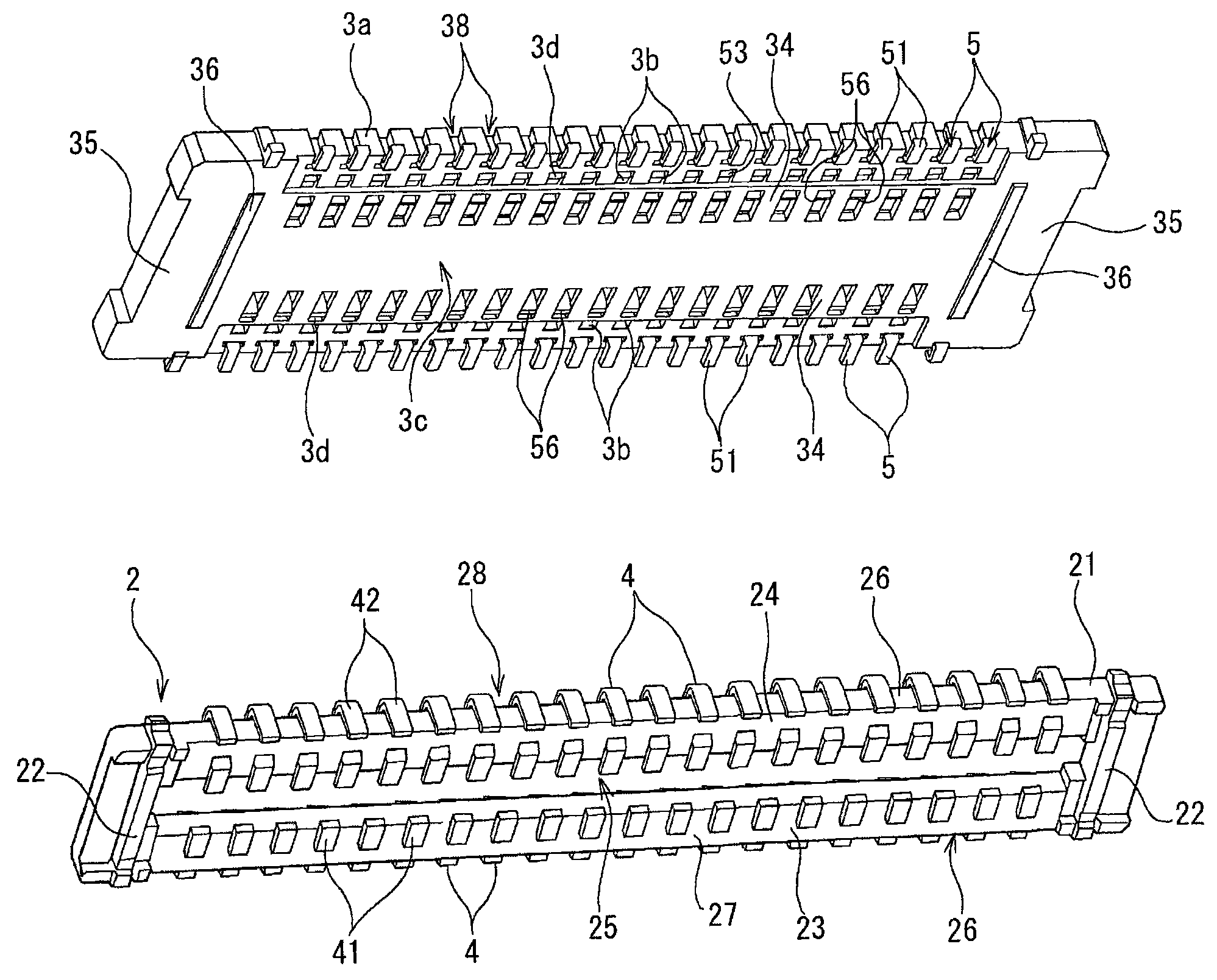
[0065] Embodiment 1 of the present invention will be described below with reference to the accompanying drawings. figure 1 is an explanatory perspective view showing Embodiment 1 of the present invention, figure 2 is a central cross-sectional explanatory diagram showing Embodiment 1 of the present invention, image 3 is an explanatory perspective view showing Embodiment 1 of the present invention, Figure 4 It is a center sectional explanatory drawing which shows the fitting state of Example 1. FIG.

[0066] Reference numeral 1 is a connector for board-to-board connection which is Example 1 of the present invention. The connector 1 for connection (hereinafter abbreviated as the connector 1) is composed of the plug 2 mounted on the second printed wiring board P2 and the connection socket 3 (hereinafter abbreviated as the first printed wiring board P1 which is the first connection object) mounted on the first printed wiring board P1. For the socket 3) configuration, the plu...

Embodiment 2

[0088] In the above-described first embodiment, the connection connector 1 is used to electrically connect the first printed wiring board P1 and the second printed wiring board P2, but in the second embodiment shown below, the purpose of connecting the first printed wiring board to the first printed wiring board is explained. The second embodiment of the structure using the plug 2 as an electronic module as an electronic component is connected to P1.

[0089] Figure 5 It is a perspective explanatory drawing which shows Example 2.

[0090] When the electronic module 2a is formed as a plug as in the second embodiment and must be connected to the printed wiring board, the electronic module 2a is sensitive to heat and has low heat resistance, and therefore cannot withstand heat such as soldering, and when repairing It must be easy to attach and detach, and the fixing to the printed wiring board by a fixing method such as soldering is not suitable. Of course, it can also be used...


PUM


Abstract

The invention provides a connector with lower back for connecting substrates. A socket contact (5) has a latch pin connection part (54) with front end positioned in a deep-inserting part to form a contact deformation preventing part (56); a latch pin contact part (55) is disposed projected on the latch pin connection part; a spring part (53) is formed in the center part of (52); an embedding concave part (31) is formed on the socket casing (33); an inserting hole (3b) for spring part is disposed on the fixing part (34); a notch part (3b) for causing it possible for the contact deformation preventing sheet part to move back and forth is disposed on the deep-inserting part side inside the fixing part; the latch pin (2) is composed of a latch pin casing (21) and a latch pin contact (4); one end of the latch pin contact (4) is positioned on outside of the latch pin casing (21), the other end is positioned on the side of the latch pin casing (21) oppositely to the latch pin contact to form a socket contact part (42); and the center part is formed on the fixing part (43) fixed on the latch pin casing.

Description

technical field [0001] The present invention relates to a connection socket used in a connection connector that can electrically connect printed wiring boards to each other or that can electrically connect an electrical module to a printed wiring board. Background technique [0002] Electronic equipment such as home appliances includes a printed wiring board on which electronic components are mounted. However, since the electronic components are mounted on only one printed wiring board, the area of ​​the board increases. Therefore, there are cases where a plurality of small boards are stacked and arranged. Constitute the condition of the device. In this case, it is necessary to electrically connect the overlapped printed wiring boards to each other with a plurality of connection terminals, and to use a multi-pole connector for board-to-board connection for electrically connecting the printed wiring boards to each other. [0003] The connection connector used for this purpos...

Claims


Application Information

Patent Timeline
IPC IPC(8): H01R12/16H01R13/193H01R33/76
CPCH01R12/52H01R12/716H01R13/26H01R13/639
Inventor 浅井清大泽文雄
Owner SMK CO LTD
Why Eureka
Try Eureka