Telescopic casing

Inactive Publication Date: 2020-10-29
HUANG CHI CHING
View PDF0 Cites 0 Cited by
  • Summary
  • Abstract
  • Description
  • Claims
  • Application Information

AI Technical Summary

Benefits of technology

The present invention is a telescopic casing designed to prevent drill direction deviation and slip during dental drilling. The technical effect is to improve the stability and precision of dental drilling.

Problems solved by technology

If the drilled location is wrong or the drilled direction of the drill 81 is shifted, it might sometimes cause a severe surgical failure; even worse, sometimes the sinus membrane within the upper jaw could be punctured, or the chin nerve of the lower jaw could be broken.

Method used


Image

  • Telescopic casing
  • Telescopic casing
  • Telescopic casing

Examples


first embodiment

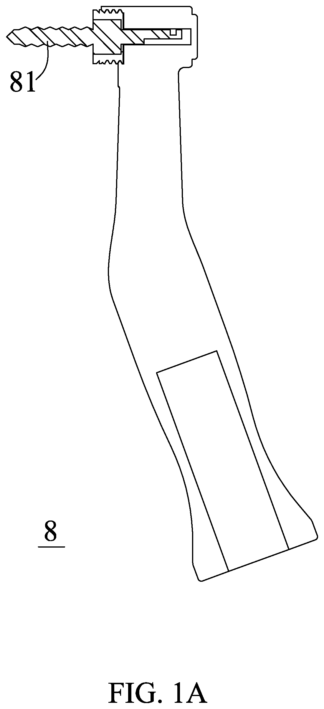
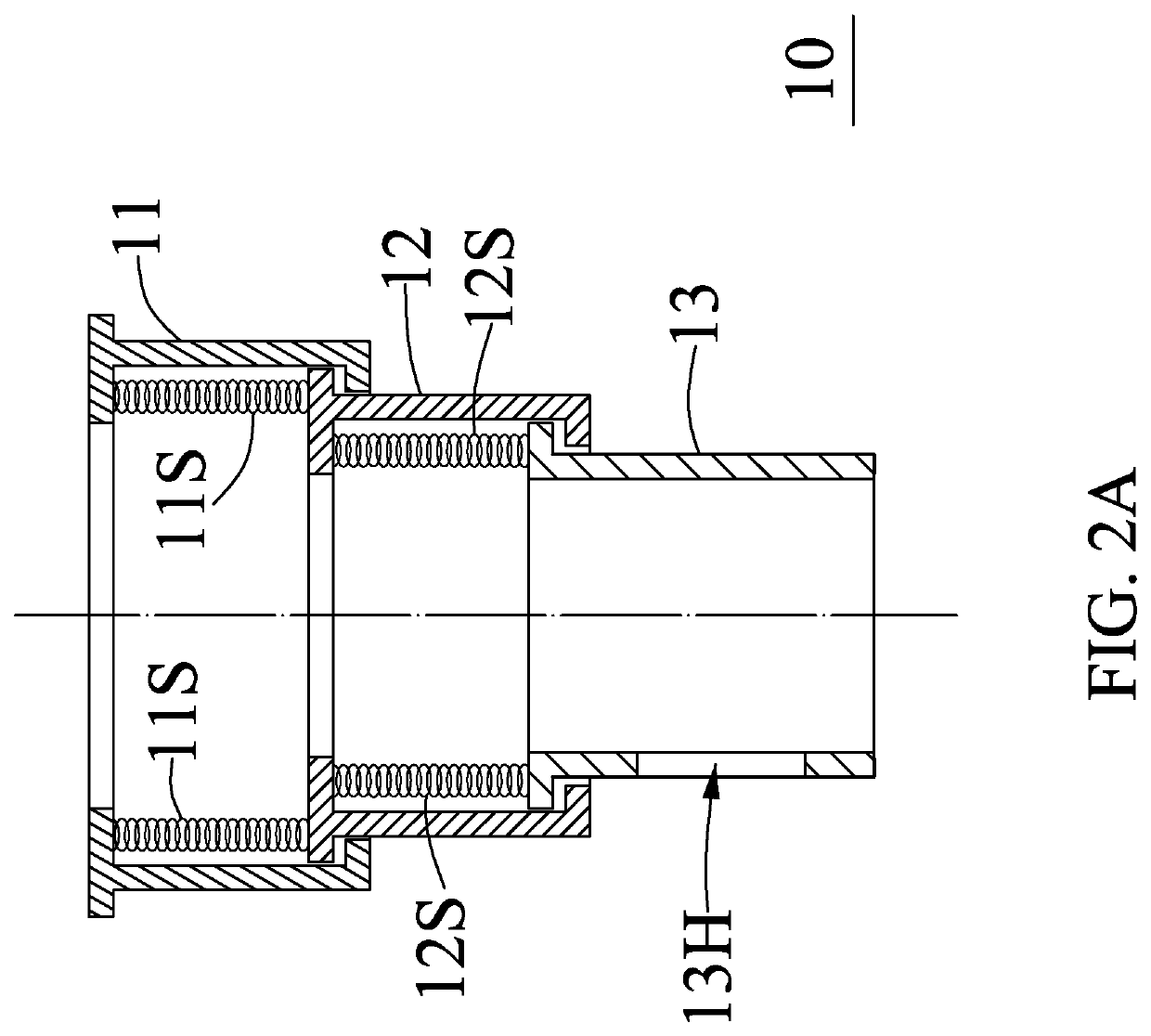
[0024]Please refer to FIG. 2A, FIG. 2B, and FIG. 2C. FIG. 2A is a cross-section view of a telescopic casing 10 according to the present invention, FIG. 2B is a three-dimensional view of the telescopic casing 10, and FIG. 2C is a schematic diagram showing the telescopic casing 10 assembled to the dental handpiece 8. As shown in FIG. 2C, the telescopic casing 10 is assembled in a dental handpiece 8. When the telescopic casing 10 is assembled in the dental handpiece 8, a drill 81 is surrounded by the telescopic casing 10. As shown in FIG. 2A and FIG. 2B, the telescopic casing 10 includes a first end portion 11, a second end portion 12, at least one first support spring 11S (two first support springs 11S are used as an example in this embodiment), a third end portion 13, and at least one second support spring 12S (two second support springs 12S are used as an example in his embodiment). The first end portion 11, the second end portion 12, and the third end portion 13 have a hollow tubul...

second embodiment

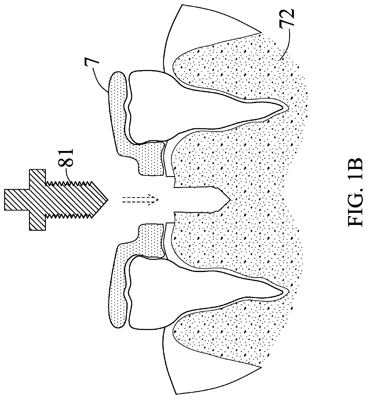
[0028]Please refer to FIG. 6A and FIG. 6B. FIG. 6A is a three-dimensional view of a telescopic casing 20 according to the present invention, and FIG. 6B is a schematic diagram showing the telescopic casing 20 being engaged with the dental implant guide plate 7. The difference between the telescopic casing 20 and the telescopic casing 10 is that: the telescopic casing 20 of the embodiment shown in FIG. 6A and FIG. B can be used to accommodate a dental implant guide plate 7. In detail, the dental implant guide plate 7 includes at least one concave hole 70 (in this embodiment, three concave holes 70 are used as an example), and the rear end of the third end portion 23 of the telescopic casing 20 includes at least one protrusion block 23C (in this embodiment, three protrusion blocks 23C are used as an example), wherein positions of the protrusion blocks 23C are corresponded to the positions of the concave hole 70, that is, the three protrusion blocks 23C correspond to the three concaves...

third embodiment

[0029]Please refer to FIG. 7A, FIG. 7B and FIG. 7C. FIG. 7A is a schematic diagram showing a telescopic casing 30 of a third embodiment being locked to the dental implant guide plate 7, FIG. 7B is a cross-sectional view showing the telescopic casing 30 locked to the dental implant guide plate 7, and FIG. 7C is a schematic diagram showing the drill 81 along the axial direction of the telescopic casing 30. The difference between the telescopic casing 30 and the telescopic casing 20 is that: the telescopic casing 30 of this embodiment can be locked to a dental implant guide plate 71 by means of a screwed mechanism. In detail, an internal screw thread 710 may be disposed on the dental implant guide plate 71, and the outer surface of the third end portion 33 of the telescopic casing 30 has an external screw thread 33C, wherein the external screw thread 33C corresponds to the internal screw thread 710. That is, the external screw thread 33C of the third end portion 33 can be screwed onto ...


PUM


Abstract

A telescopic casing includes first end portion, second end portion, first support spring, third end portion, and second support spring. Each of the first, second, and third end portions has a hollow tubular shape. Top end of first end portion is detachably coupled to dental handpiece. Top end of second end portion is nested by rear end of first end portion. First support spring is disposed in first end portion, wherein one end of first support spring abuts against top end of second end portion and the other end of first support spring abuts against first end portion. Top end of third end portion is nested by rear end of second end portion. Second support spring is disposed in second end portion, wherein one end of second support spring abuts against top end of third end portion and the other end of second support spring abuts against second end portion.

Description

BACKGROUND OF THE INVENTIONField of the Disclosure[0001]The present disclosure relates to a telescopic casing, and more particularly to a telescopic casing for assisting dental implant surgery.Description of Related Art[0002]Please refer to FIG. 1A and FIG. 1B. FIG. 1A is a schematic diagram of a conventional dental handpiece 8, and FIG. 1B is a cross-sectional view of a drilling performed by a drill 81 of the dental handpiece 8 in cooperation with a dental implant guide plate 7. The dental handpiece 8 is the lowest-risk and first-grade medical device in dental clinical treatment. It can be used to drill a hole within a tooth for accommodating to fill the implant. The dental handpiece 8 can be utilized to accompany with the dental implant guide plate 7 when drilling, so as to align the drill 81 with the exact right position of the tooth socket 72. In this manner, the successful rate of dental surgery is therefore improved, and the medical risk is thus reduced. Since the dental handp...

Claims


Application Information

Patent Timeline
IPC IPC(8): A61C1/08A61C8/00
CPCA61C8/0089A61C1/084
Inventor HUANG, CHI-CHINGKAO, MEI-HUI
Owner HUANG CHI CHING
Why Eureka
Try Eureka