Grinder arrangement and method for pivoting a grinding spindle unit

A grinding machine, pivoting shaft technology, applied in the field of grinding machine devices, can solve the problems of affecting grinding results, fluctuations in rotation speed, differences, etc.

Active Publication Date: 2016-04-20
ERWIN JUNKER MASCHNINENFAB
View PDF9 Cites 0 Cited by
  • Summary
  • Abstract
  • Description
  • Claims
  • Application Information

AI Technical Summary

Problems solved by technology

For unequal loads, fluctuations in rotational speed are also unavoidable, which can likewise adversely affect the grinding results
An additional disadvantage may be that the optimal rotational speed for the effect of the shape change of the grinding wheel is often different from the rotational speed required for optimal grinding results

Method used


Image

  • Grinder arrangement and method for pivoting a grinding spindle unit
  • Grinder arrangement and method for pivoting a grinding spindle unit
  • Grinder arrangement and method for pivoting a grinding spindle unit

Examples


Embodiment Construction

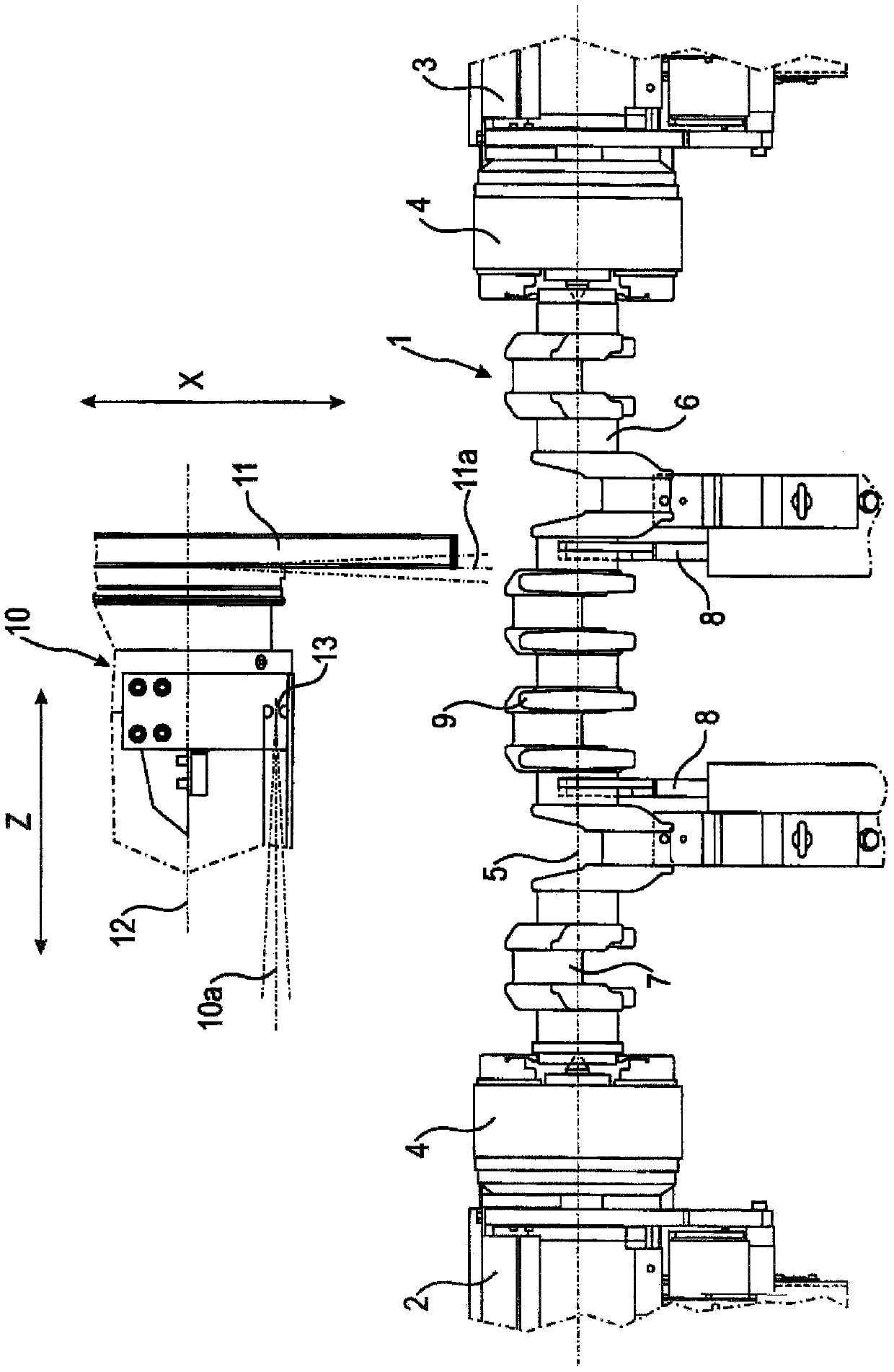
[0052] exist figure 1In , the crankshaft 1 of a 6-cylinder internal combustion engine is shown as a workpiece, which is clamped for grinding between a workpiece headstock 2 and a tailstock 3 . Both the workpiece headstock 2 and the tailstock 3 have a chuck 4 with complementary chuck jaws and tips; the crankshaft 1 is thus driven in rotation about its longitudinal axis 5 extending through the main bearing 6 . The crankshaft 1 has seven main bearings 6 and six pin bearings 7 ; the two main bearings 6 are supported here via fastening brackets 8 . The main and pin bearings 6 , 7 are interconnected by crank arms 9 . The grinding spindle unit 10 extends along the crankshaft 1, only at figure 1 The end region of the grinding spindle unit 10 positioned on one side of the grinding wheel 11 is shown in . Reference numeral 12 designates the axis of rotation of the grinding wheel 11 , which is produced by the drive shaft to which the grinding wheel 11 is fixed.

[0053] The normal pos...


PUM


Abstract

The housing ( 28 ) of the grinding spindle unit is mounted pivotably via a pivot axis ( 26 ) on a receptacle ( 21 ) of the grinding machine, for example on a grinding headstock. The grinding spindle unit supports a rotationally driven grinding wheel (31). Actuation of the adjustment unit (33) extends the press-in pin (34), which pivots the housing (28) of the grinding spindle unit about the pivot axis (26) and thus tilts the grinding wheel (31). The pivot axis ( 26 ) is in this case formed as a film hinge passing through the deformation zone of the targeted elastic material. The tension spring arrangement (38) produces a constant contact between the press-in pin (34) and the receptacle (21). The rotation arrow (36) indicates the pivoting direction and the rotation arrow (37) indicates the angle at which the grinding spindle unit is inclined relative to the receptacle (21). The axis of the rotating workpiece (not shown) is indicated by reference numeral (22).

Description

technical field [0001] The invention relates to a grinding machine arrangement having a grinding spindle unit with a motor-driven drive shaft supported therein and a grinding wheel fastened to one end thereof, the grinding spindle unit being pivotably supported On the receptacle of the grinding machine, different inclinations of the drive shaft relative to the reference line are provided by means of the pivotable mounting. [0002] The invention also relates to a method for pivoting a grinding spindle unit connected via at least one pivot shaft to a housing of a grinding machine and having a motor-driven drive shaft and an additional The grinding wheel at one end, whereby the grinding spindle unit is pivoted, sets a different inclination of the drive shaft relative to the reference line. Background technique [0003] According to the prior art, the pivotable mounting of a grinding spindle unit of this type on a grinding machine consists in the fact that the grinding spindle...

Claims


Application Information

Patent Timeline
Patent Type & Authority Patents(China)
IPC IPC(8): B23Q1/34B23Q1/36B24B5/42B24B19/12B24B41/04
CPCB23Q1/34B23Q1/36B23Q2210/002B24B5/42B24B41/04
Inventor 埃尔温·容克尔
Owner ERWIN JUNKER MASCHNINENFAB
Why Eureka
Try Eureka