
Method and device for transmitting IP message through transmission network

A technology of IP message and transmission network, applied in the field of network communication

Inactive Publication Date: 2009-08-26
深圳市智通天下科技服务有限公司
View PDF0 Cites 6 Cited by
  • Summary
  • Abstract
  • Description
  • Claims
  • Application Information

AI Technical Summary

Problems solved by technology

[0009] Embodiments of the present invention provide a method and device for transmitting IP packets through a transmission network to solve the problem of separating the establishment of UNI services from the establishment of IP services on a border router

Method used


Image

  • Method and device for transmitting IP message through transmission network
  • Method and device for transmitting IP message through transmission network
  • Method and device for transmitting IP message through transmission network

Examples


Embodiment 1

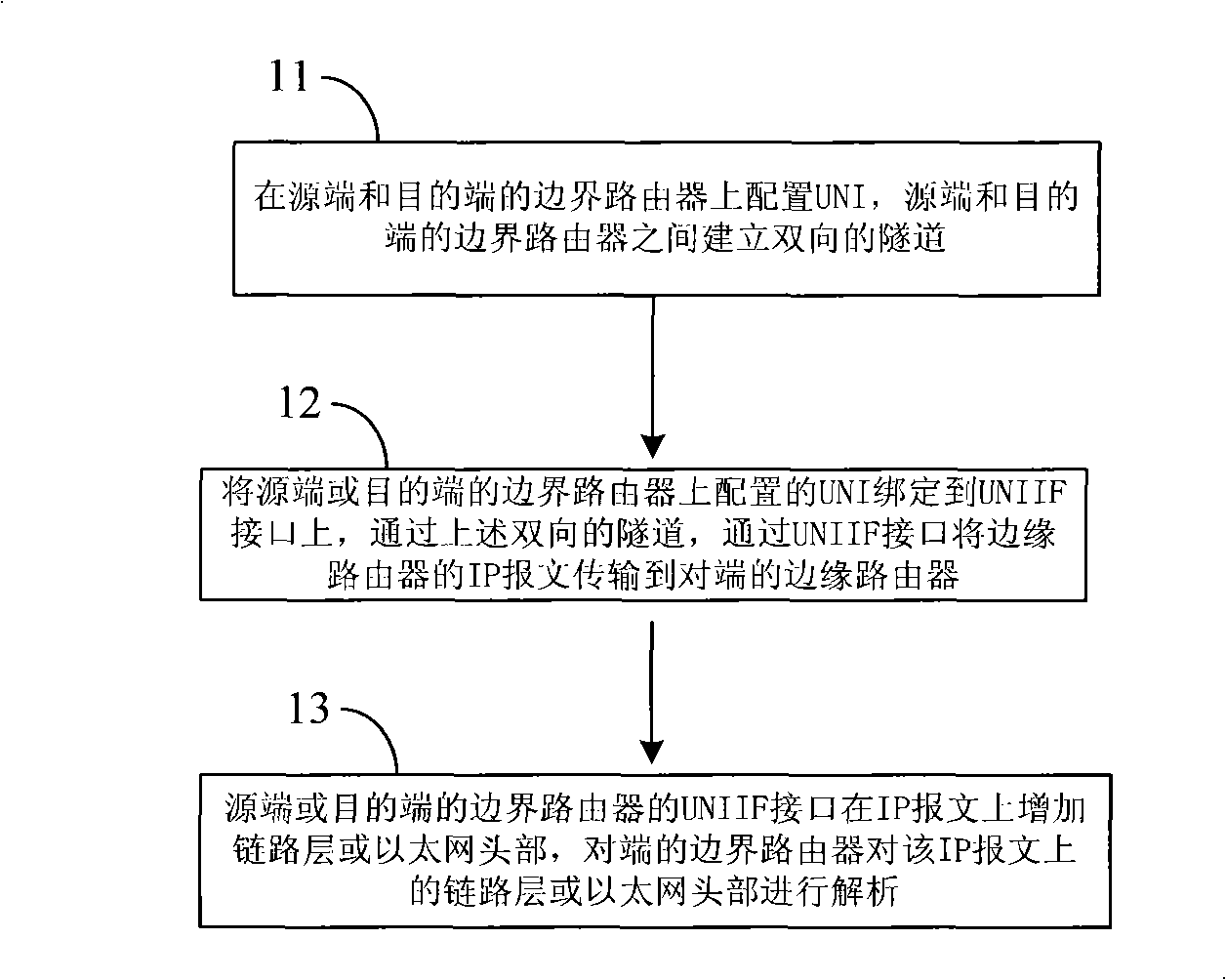
[0025] The processing flow of a method for transmitting an IP message through a transmission network provided by this embodiment is as follows: figure 1 As shown, the following processing steps are included:

[0026] Step 11, configure UNI on the border routers at the source end and the destination end, and establish a bidirectional tunnel between the border routers at the source end and the destination end.

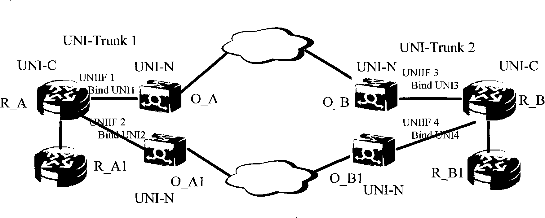
[0027] Configure the UNI on the UNI-C (the UNI connected to the client) at the source or destination, including configuring the parameters needed to establish an end-to-end UNI service, such as source and destination IP addresses, desired bandwidth, protection mode, etc. After the above UNI is configured, between the UNI-C at the source end and the UNI-C at the destination end, protocols such as RSVP on the router interact with protocols such as RSVP on the equipment in the transmission network to establish a bidirectional end-to-end traversal transmission network The t...

Embodiment 2

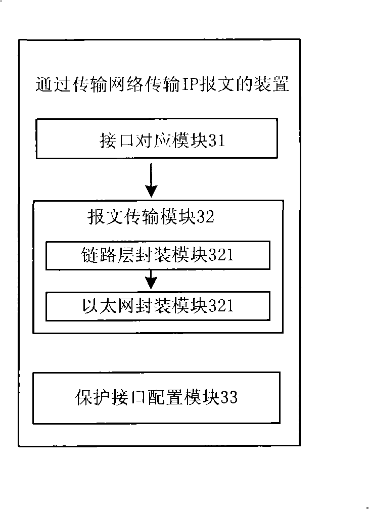
[0049] This embodiment provides a device for transmitting IP packets through a transmission network, and its specific implementation structure is as follows: image 3 As shown, it may specifically include:

[0050] The interface corresponding module 31 is used to pre-configure the parameters required to establish the UNI service of the user network node on the edge routers of the source end and the destination end in the general multi-protocol label switching network, and establish a link from the source end router to the destination end router according to the parameters. A bidirectional tunnel, the bidirectional tunnel passing through the transmission network; creating a UNIIF interface from the UNI to the transmission network on the edge routers of the source and destination, and the UNIIF interface corresponds to the connection between the source router and the destination router bi-directional tunnel;

[0051] A message transmission module 32, configured to enter the IP ...


PUM


Abstract

The embodiment of the invention provides a method and a device for transmitting IP message through transmission network. An UNIIF (access from UNI to a transmission network) interface is created on edge routers of a source terminal and a objective terminal in a general multiprotocol label switching network, and the UNIIF interface corresponds to a bidirectional tunnel between the source terminal router and the objective terminal router. The IP message of the edge router of the source terminal or the objective terminal enters the tunnel through the UNIIF interface, and IP message is transmitted to a edge router of a opposite terminal through the tunnel. The present invention realizes transmission of the IP business message through the transmission network and guarantees isolation of the establishment of the UNI business on a border router and establishment of IP business.

Description

technical field [0001] The invention relates to the technical field of network communication, in particular to a method and device for transmitting IP messages through a transmission network. Background technique [0002] In traditional transmission networks, services are established through static configuration. With the continuous development of 3G (The third Generation Mobile Telecommunication, third-generation mobile communication network), packet services, and broadband services, not only the demand for network bandwidth Increasingly large, and due to the increasing uncertainty and unpredictability of services, there are more and more requirements for dynamic and automatic path establishment and bandwidth adjustment. In this case, traditional static configuration services cannot adapt to the form development of. The GMPLS (Generalized Multi-Protocol Label Switching, Generalized Multi-Protocol Label Switching) network is produced under such circumstances. [0003] From...

Claims


Application Information

Patent Timeline
IPC IPC(8): H04L29/06H04L12/56H04L12/70
Inventor 何路友熊怡孙俊柏
Owner 深圳市智通天下科技服务有限公司
Learn More