Sharing IP network resources

a technology of ip network resources and backbone networks, applied in data switching networks, high-level techniques, instruments, etc., can solve the problems of affecting the bandwidth available to other isp users, affecting the efficiency and practicality of channel allocation to particular isps, and the upstream frequency spectrum of cable networks available to cable modems is limited to frequencies below 80 mhz. , to achieve the effect of efficient sharing of customer access and backbone networks

Inactive Publication Date: 2006-02-23
AT HOME BONDHOLDERS LIQUIDATING TRUST
View PDF99 Cites 21 Cited by
  • Summary
  • Abstract
  • Description
  • Claims
  • Application Information

AI Technical Summary

Benefits of technology

[0017] When the border router receives a packet, it pops off the label and forwards the unlabeled packet to the appropriate ISP. If desired, traffic accounting can be performed by counting the packets forwarded to the ISP by the border router. Accordingly, the present invention allows multiple ISPs to efficiently share the customer access and backbone networks.

Problems solved by technology

However, the entities that own the broadband network infrastructure have been reluctant to share network access with other ISPs due, in part, to the difficulty in sharing the bandwidth on the cable network.
Bandwidth on the customer access network, while broadband, is not unlimited, and heavy use by the end-users of one ISP can impact the bandwidth available to the users of other ISPs.
However, the upstream frequency spectrum on a cable network available to cable modems is limited to frequencies below 80 MHz.
It is inefficient and impractical to allocate channels to particular ISPs since ISPs with many end-users would require more bandwidth than is available in a channel while the channels of ISPs having few end-users would be underutilized.

Method used


Image

  • Sharing IP network resources
  • Sharing IP network resources
  • Sharing IP network resources

Examples


Embodiment Construction

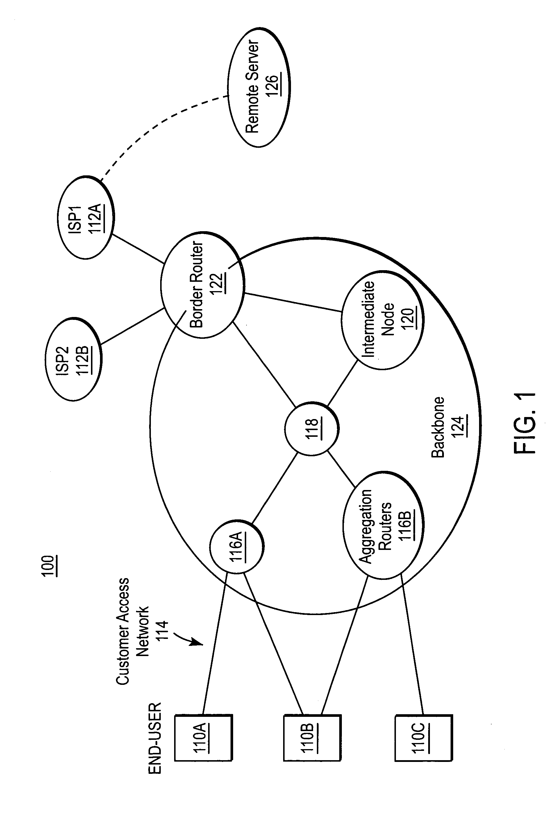
[0023]FIG. 1 is a block diagram illustrating a high-level view of a network infrastructure 100 according to an embodiment of the present invention. FIG. 1 illustrates three end-users 110A, 110B, 110C connected to the network. As used herein, the term “end-user” can refer to a person using a computer system to connect to the network, the computer system itself, or a network access device, such as a modem, connecting the computer system to the network. In a typical use, a person will direct the computer system to send data out to a network and the computer will utilize the network access device to send the data. Data from an end-user 110 typically consists of Internet protocol (IP) data packets.

[0024] In one embodiment of the present invention, the network access device is either a cable modem or a digital subscriber line (DSL) modem. However, the present invention supports any form of network access device providing the functionality described herein. In a preferred embodiment of th...


PUM


Abstract

A system and method for sharing access to an internet protocol (IP) network among multiple internet service providers (ISPs) uses multiprotocol label switching (MPLS). End-users are coupled to a broadband customer access network. Each end-user is also associated with at least one of the ISPs. An aggregation router interfaces the customer access network with a network backbone. The network backbone includes a border router for interfacing between the network backbone and the network of an ISP. When the border router is activated, it creates a forwarding equivalency class (FEC) corresponding to the ISP. The border router stores a label for the FEC and the interface for reaching the ISP in an FEC table. The border router advertises the label binding for the FEC to all upstream nodes. An intermediate node receiving the label binding creates its own FEC table, associates a new label with the FEC, and advertises the new label binding to its upstream nodes. The aggregation router receives and builds a FEC table containing the label bindings for all ISPs reachable over the network backbone. When the aggregation router receives a data packet from an end-user, the aggregation router determines the ISP associated with the end-user, labels the data packet with the label corresponding to the FEC for that ISP, and routes the packet on the network backbone. The packet eventually reaches the border router, which pops off the label and passes the packet to the ISP.

Description

CROSS-REFERENCE TO RELATED APPLICATION [0001] This application claims priority under 35 U.S.C. §120 to U.S. patent application Ser. No. 09 / 645,011, filed on Aug. 23, 2000, entitled SHARING IP RESOURCES by Jeremy T. Johnson, et al., the contents of which are herein incorporated by reference in its entirety.BACKGROUND [0002] 1. Field of the Invention [0003] This invention pertains in general to computer networks and in particular to a broadband network for coupling end-users to Internet service providers. [0004] 2. Background Art [0005] In recent years, there has been substantial growth in broadband Internet access. In the traditional sense, “broadband” refers to a transmission medium capable of supporting a wide range of frequencies. In more common parlance, however, “broadband” refers to a transmission medium capable of supporting a high data transfer rate. An example of a broadband network is a cable modem network. [0006] In a broadband network, the network infrastructure closest t...

Claims


Application Information

Patent Timeline
Patent Type & Authority Applications(United States)
IPC IPC(8): G06F15/173H04L45/50
CPCH04L12/2856H04L12/2863H04L47/787Y02B60/33H04L45/30H04L45/50Y02D30/50
Inventor JOHNSON, JEREMY T.MEDIN, MILO S.
Owner AT HOME BONDHOLDERS LIQUIDATING TRUST
Why Eureka
Try Eureka