
LSP hierarchy for MPLS networks

a multi-protocol label switching and label switching technology, applied in the field of data processing, can solve the problems of expensive and time-consuming network upgrade, many networks do not support gmpls,

Active Publication Date: 2013-05-28
JUMIPER NETWORKS INC
View PDF13 Cites 22 Cited by
  • Summary
  • Abstract
  • Description
  • Claims
  • Application Information

AI Technical Summary

Benefits of technology

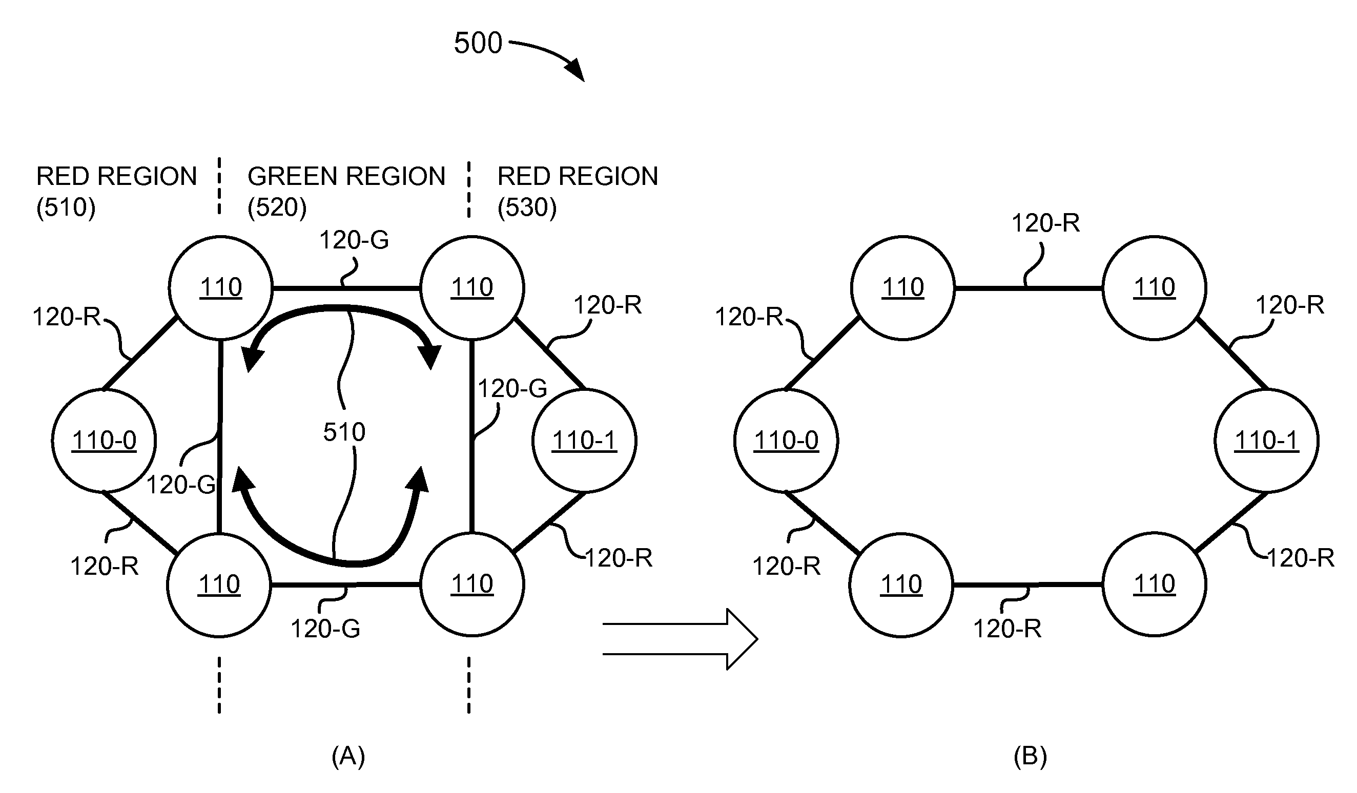
This patent describes a method and system for creating a blueprint for a multiprotocol label switching (MPLS) network, which is a type of network used for traffic engineering. The method involves coloring links in the network with different colors to define regions, and using these regions to create a boundary that triggers the creation of a new path for traffic. This boundary can be based on the pattern of colors used to define the regions. The system includes a device that can determine if a link is within a specific region and create a new path based on this information. The technical effect of this patent is to enable more efficient traffic engineering in MPLS networks.

Problems solved by technology

However, many networks do not support GMPLS and only support MPLS.
Unfortunately, a LSP hierarchy relies on GMPLS signaling and routing extensions that are not compatible with existing MPLS networks.
Deploying a LSP hierarchy in a MPLS network would require that all routers in the network be upgraded to support GMPLS, a costly and time consuming network upgrade.

Method used


Image

  • LSP hierarchy for MPLS networks
  • LSP hierarchy for MPLS networks
  • LSP hierarchy for MPLS networks

Examples


example 1

Diverse Path Calculation Example 1

[0067]As shown in FIG. 8, a MPLS network 800 may include network devices 110-1, . . . , 110-8 interconnected by links L1, L3, . . . , L11. Network 800 may include a primary LSP 810, and two FA-LSPs 820 and 830. Primary LSP 810 may, for example, traverse links L3, L4, L8, and L10. FA-LSPs 820 and 830 may advertise links L4-L8 as one TE link, and a LSP may only see FA-LSPs 820 and 830 as a TE link between network devices 110-3 and 110-6.

[0068]In this arrangement, it may be desired that a secondary LSP be created that may travel a path diverse from the path taken by primary LSP 810. However, due to FA-LSP 820, a secondary LSP 840 may traverse a path that may have links (e.g., links L4 and L8) that may be common to links traversed by primary LSP 810. In order to create a secondary LSP diverse from primary LSP 810, an administrative group policy may be implemented that may exclude links L4 and L6 from the calculation of the path for the secondary LSP. Fo...

example 2

Diverse Path Calculation Example 2

[0069]As shown in FIG. 9, a MPLS network 900 may include network devices 110-1, . . . , 110-8 interconnected by links L1, L3, . . . , L11. Network 900 may include a primary LSP 910, and two FA-LSPs 920 and 930. Primary LSP 910 may, for example, traverse links L3, L4, L8, and L10. FA-LSPs 920 and 930 may advertise links L4-L8 as one TE link, and a LSP may only see FA-LSPs 920 and 930 as a TE link between network devices 110-3 and 110-6.

[0070]In this arrangement, it may be desired that a secondary LSP be created that may travel a path diverse from the path taken by primary LSP 910. However, due to FA-LSP 930, a secondary LSP 940 may traverse a path that may have a common link (e.g., link L8) with primary LSP 910. In order to create a secondary LSP diverse from primary LSP 910, the concepts of fate sharing and Shared Risk Link Groups (SRLGs) may be implemented to exclude links L4 and L6 from the calculation of the path for a secondary LSP 950. The MPLS...


PUM


Abstract

A system may define a first region that includes a first colored link of a multiprotocol label switching (MPLS) network, and may define a second region that includes a second colored link of the MPLS network. The system may define a boundary between the first and second regions based on the first colored link and the second colored link.

Description

BACKGROUND[0001]1. Field of the Invention[0002]Implementations consistent with principles of the invention relate generally to data processing and, more particularly, to a label switched path (LSP) hierarchy for Multiprotocol Label Switching (MPLS) networks.[0003]2. Description of Related Art[0004]In a Multiprotocol Label Switching (MPLS) network, a signaling protocol may be used to set up a label switched path (LSP) in the MPLS network. MPLS may permit a network to direct a flow of datagrams along a predetermined path (e.g., a LSP) across the network. A “datagram(s)” may include any type or form of data, such as packet or non-packet data. As part of setting up the LSP, label switching routers (LSRs) included in the MPLS network may set up a label information base (LIB) which may map an incoming label from an input port of the LSR to an output port of the LSR and to a new label value. The LSRs may forward datagrams along links through the MPLS network based on labels attached to the...

Claims


Application Information

Patent Timeline
Patent Type & Authority Patents(United States)
IPC IPC(8): H04L12/28
CPCH04L45/50H04L45/04H04L47/785H04L47/724
Inventor AYYANGAR, ARTHI
Owner JUMIPER NETWORKS INC
Learn More