Indoor unit of air conditioner

A technology for indoor units and air conditioners, applied in air conditioning systems, refrigerators, compressors, etc.

Active Publication Date: 2009-08-26
DAIKIN IND LTD
View PDF0 Cites 3 Cited by
  • Summary
  • Abstract
  • Description
  • Claims
  • Application Information

AI Technical Summary

Problems solved by technology

Also, because the gas-liquid two-phase region where the latent heat changes is longer, the region where the refrigerant at the same temperature flows in the heat exchanger is longer

Method used


Image

  • Indoor unit of air conditioner
  • Indoor unit of air conditioner
  • Indoor unit of air conditioner

Examples


Embodiment approach 1

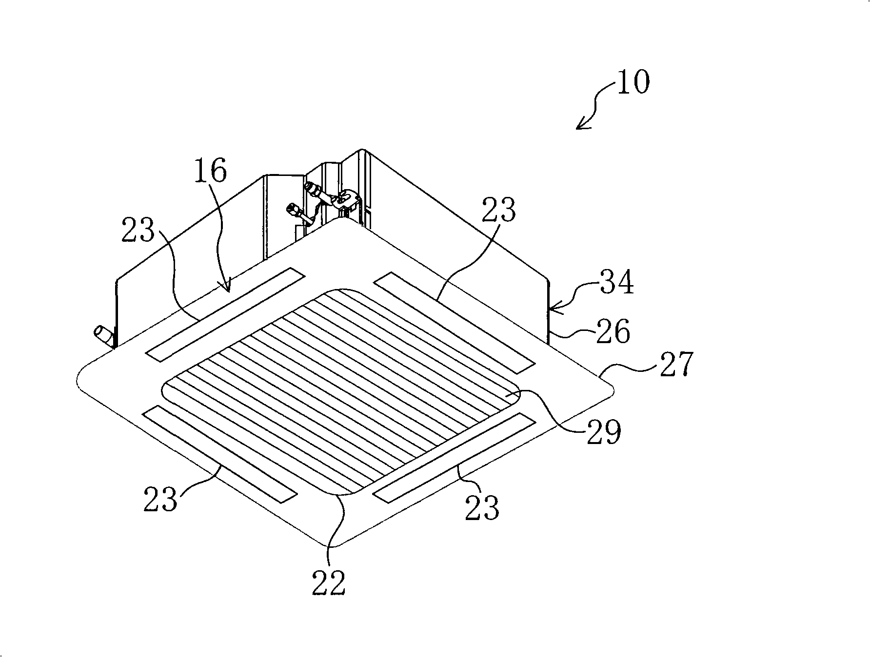
Embodiment 1 of the present invention will be described. Embodiment 1 is an indoor unit 10 of an air conditioner according to the present invention. Such as figure 1 As shown, the indoor unit 10 of the air conditioner according to Embodiment 1 is an indoor unit 10 in which four air outlets 23 are formed along each side of a decorative panel 27 to blow air in four directions. The four outlets 23 constitute the outlet 16 .

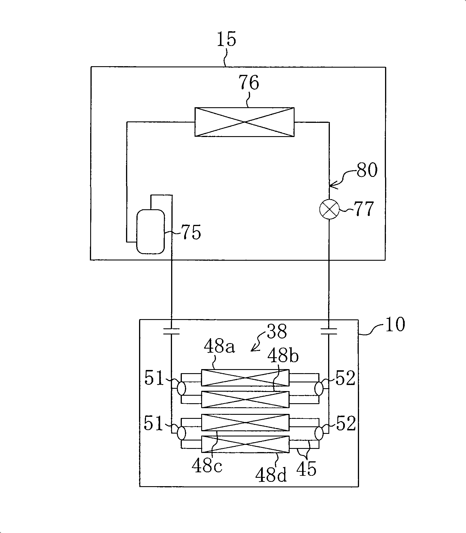
[0070] Such as figure 2 As shown, this indoor unit 10 is connected to a refrigerant circuit 80 together with an outdoor unit 15 that accommodates a compressor 75 , an outdoor heat exchanger 76 , and an expansion valve 77 . This refrigerant circuit 80 is filled with carbon dioxide as a refrigerant. This air conditioning mechanism becomes capable of heating operation. In addition, a four-way reversing valve may be provided in the refrigerant circuit 80 so that the air conditioner can selectively perform heating operation and cooling operation.

[0071]T...

Embodiment approach 2

Embodiment 2 of the present invention will be described. Embodiment 2 is an indoor unit 10 of an air conditioner according to the present invention. Differences from Embodiment 1 described above will be described below.

[0103] In Embodiment 2, if Figure 8 As shown, the heat exchange unit 38 is composed of one heat exchanger 48 formed in the shape of a "mouth" when viewed from a plan view. The heat exchanger 48 is arranged to surround the side of the indoor fan 39 . In addition, in this heat exchanger 48 , U-shaped heat transfer tubes (outer diameter 7 mm) having a wall thickness of about 1 mm are used as in the modified example of the first embodiment described above. In addition, at the three bends of the heat exchanger 48, the bend radius is set to a value of about 80 mm.

[0104] Such as Figure 9 , Figure 10 As shown, eight refrigerant flow passages 45 , 45 , . Also, eight refrigerant flow passages 45 are arranged along the axial direction of the indoor fan 39 . ...


PUM


Abstract

An indoor unit for a multi-directional air supply air conditioner capable of performing at least a heating operation includes: an indoor fan (39) for sucking air in an axial direction thereof and radially blowing out the air; and a heat exchange part (38), connected in a refrigerant circuit (80) and disposed to surround the indoor fan (39), for exchanging heat between the air blown out of the indoor fan (39) and refrigerant in the refrigerant circuit (80). The heat exchange part (38) includes a plurality of heat exchangers (48) separated from each other along the direction of the perimeter thereof and connected in parallel with each other in the refrigerant circuit (80).

Description

technical field [0001] The present invention relates to an indoor unit including an air conditioner that blows air in a plurality of directions different from each other. Background technique [0002] Heretofore, an indoor unit of an air conditioner is known in which an air-conditioning unit is formed with a blowing unit that blows air in a plurality of directions different from each other. In such an indoor unit, for example, blowout ports constituting a blowout portion are formed along each side of the lower surface of the indoor unit. Such an indoor unit is disclosed in Patent Document 1. [0003] Specifically, the indoor unit disclosed in Patent Document 1 is an indoor unit capable of cooling operation and heating operation. The indoor unit includes a box-shaped casing. A blower and a heat exchanger are accommodated in the casing. The blower is also called a turbo fan. The blower is provided at the center of the case. The heat exchanger is a tube-fin heat exchanger...

Claims


Application Information

Patent Timeline
IPC IPC(8): F24F13/30F24F1/00F25B1/00F24F1/0063
CPCF24F2001/0037F24F1/0059F25B39/00F25B9/008F25B2309/061F28D1/0426F28D1/0475F24F2013/0616F24F2221/54F24F1/0047F24F1/0063F24F13/30F24F1/00F25B1/00
Inventor 吉冈俊金鉉永铃木智博笠井一成中田春男
Owner DAIKIN IND LTD
Why Eureka
Try Eureka