Electrodeless discharge lamp, and lighting equipment, and method for manufacturing electrodeless discharge lamp

A discharge lamp and electrodeless technology, applied in lighting devices, gas discharge lamp parts, discharge lamps, etc., can solve the problems of controlling the coldest spot temperature, temperature rise, light output drop, etc.

Inactive Publication Date: 2009-08-26
MATSUSHITA ELECTRIC WORKS LTD
View PDF3 Cites 1 Cited by
  • Summary
  • Abstract
  • Description
  • Claims
  • Application Information

AI Technical Summary

Problems solved by technology

However, when the bulb is lit downwards (i.e. in an orientation such that the base deployed in the bulb is arranged to face upwards), the temperature of the bump increases due to the bump being deployed on top of the bulb, so that the raised part is no longer the coldest spot
Therefore, when the bulb is lit downwards, the light output may drop as the temperature of the coldest spot cannot currently be controlled by the raised portion
Also, the output may vary depending on the lighting direction of the lamp

Method used


Image

  • Electrodeless discharge lamp, and lighting equipment, and method for manufacturing electrodeless discharge lamp
  • Electrodeless discharge lamp, and lighting equipment, and method for manufacturing electrodeless discharge lamp
  • Electrodeless discharge lamp, and lighting equipment, and method for manufacturing electrodeless discharge lamp

Examples


Embodiment Construction

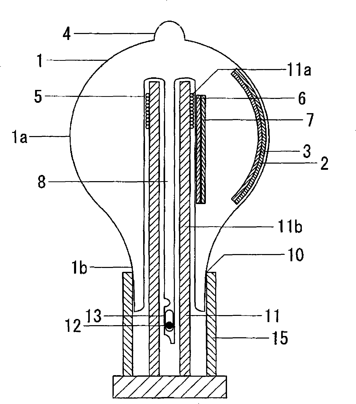
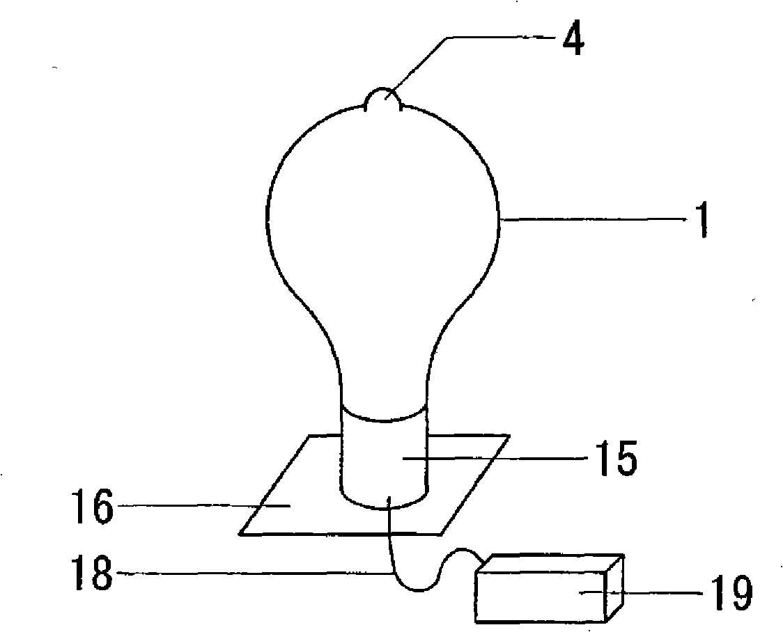
[0040] figure 1 A cross-sectional view of the electrodeless discharge lamp of this embodiment is shown. figure 2 A schematic diagram of a lighting device including the lamp of this embodiment is shown.

[0041] The electrodeless discharge lamp includes a bulb 1 made of a light-transmitting material such as glass, and mercury and an inert gas such as argon or krypton are enclosed inside the bulb 1 .

[0042] The sealed bulb 1 comprises: a substantially spherical bulb 1a; a neck 1b extending from the bulb 1a; a cavity 5 extending from the neck 1b to the bulb 1a, in which is inserted a coupling described below. device 11; a fine exhaust pipe 8 disposed inside the cavity 5, and the thin exhaust pipe 8 runs from the bottom of the cavity 5 toward the opening of the cavity.

[0043] The boss 4 is on the opposite side of the neck 1b (ie, on the figure 1 The upper end of the spherical portion 1a) is formed on the top end of the spherical portion 1a, and protrudes to the outside of th...


PUM


Abstract

The electrodeless discharge lamp of the present invention comprises: a bulb 1 provided with a substantially-spherical spherical portion 1a and a neck portion 1b extending from the spherical portion; a base 15 connected to the neck portion; a protrusion 4 formed at an apex of the spherical portion; and an induction coil 11a that causes light emission by discharge developed in the bulb. When defining the relations B=W / (4*pi(D / 20) ), S=pi*(d / 20) , L=pi*(d / 10), X=(B*S) / (L*A), where W (W) denotes the lamp input power, D (mm) denotes the diameter of the spherical portion, d (mm) denotes the diameter of a portion at a joint surface between the neck portion and the base, and A (mm) denotes the distance from a largest-diameter portion of the spherical portion to the joint surface, then the electrodeless discharge lamp satisfies the formula below: t - 6 <= 10959*X + 25 <= t + 6 where t is the temperature (DEG C) at the tip of the protrusion 4 during downward stable lighting of the electrodeless discharge lamp.

Description

technical field [0001] The present invention relates to an electrodeless discharge lamp in which a bulb has no electrodes, and to a lighting device using the electrodeless discharge lamp and a method for manufacturing the same Enclosed with an inert gas and luminescent material, it emits light by causing a discharge in the bulb by applying a high-frequency electromagnetic field to the bulb, generated by a high-frequency current in an induction coil. Background technique [0002] Electrodeless discharge lamps consist of a bulb and an induction coil. Inert gas and luminescent material are enclosed in the bulb. Examples of electrodeless fluorescent lamps include, for example, lamps in which an induction field generated by a high-frequency current flowing through an induction coil causes a discharge in a bulb, thereby exciting mercury as a light-emitting material. Ultraviolet radiation from the excited mercury atoms then strikes the phosphor, whereby the ultraviolet radiation ...

Claims


Application Information

Patent Timeline
Patent Type & Authority Applications(China)
IPC IPC(8): H01J65/04F21Y101/00F21S2/00
CPCH01J5/56H01J61/30H01J65/048H01J65/04H01J65/044
Inventor 都筑佳典酒井和彦平松宏司冈田淳典
Owner MATSUSHITA ELECTRIC WORKS LTD
Why Eureka
Try Eureka