Interface detection method based on optical interface detector

A detection method and optical interface technology, applied in scientific instruments, material analysis through optical means, instruments, etc., can solve the problems of large signal fluctuations, weak optical signals, low resolution, etc., and achieve obvious effects, good stability, Apply flexible effects

Active Publication Date: 2021-08-03
PIPECHINA SOUTH CHINA CO +2
View PDF4 Cites 0 Cited by
  • Summary
  • Abstract
  • Description
  • Claims
  • Application Information

AI Technical Summary

Problems solved by technology

[0008] The invention provides an interface detection method based on an optical interface detector, which is used to solve the problem that when the prior art is applied to an intelligent oil interface detector, the optical signal is very weak, the signal fluctuates greatly, is unstable, and the resolution is low. The technical scheme is as follows:

Method used


Image

  • Interface detection method based on optical interface detector
  • Interface detection method based on optical interface detector
  • Interface detection method based on optical interface detector

Examples


Embodiment 1

[0045] Embodiment one: calibration and test method of the present invention

[0046] As attached to the manual figure 1 Shown:

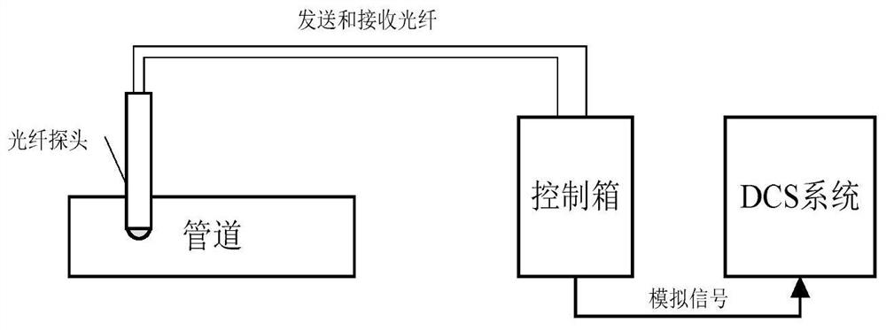
[0047] Step 1: Connect the output end and input end of the fiber optic probe to the optical sending and receiving devices in the control box respectively. The distance between the probe and the control box is 10m (2km), and connect the output signal of the control box to the DCS end;

[0048] Step 2: Prepare several bottles that are completely protected from light, fill the bottles with several media that need to be tested, and mark them well. During this process, the media cannot be exposed to light, and the better the shading of the bottle, the more accurate the test results higher;

[0049] Step 3: Wipe the fiber optic probe clean, power on the control box, set the system temperature, wait for the temperature in the control box to be constant, and then insert the probe into the water. At this time, the signal value will be displayed on the scre...

Embodiment 2

[0053] Embodiment 2: The present invention is based on the interface detection method of the optical interface detector

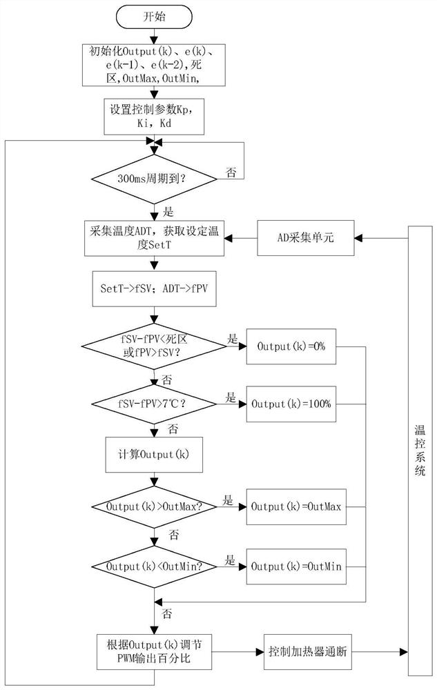
[0054] (1) Temperature control

[0055] As attached to the manual figure 2 As shown in the control box, the luminous and photoelectric conversion areas are heated, internally circulated, and heat-insulated, and a temperature detection chip is installed near the semiconductor laser to obtain the real-time temperature of the area. According to the temperature and the set temperature, The closed-loop temperature control algorithm is used to adjust the PWM output percentage to control the on-off of the heater, and finally make the area in a constant temperature state. When the difference between the actual temperature and the target temperature is greater than 7°C, full-speed heating is adopted to save the heating time of the system, and when it is less than 7°C, it enters closed-loop temperature control to adjust heating.

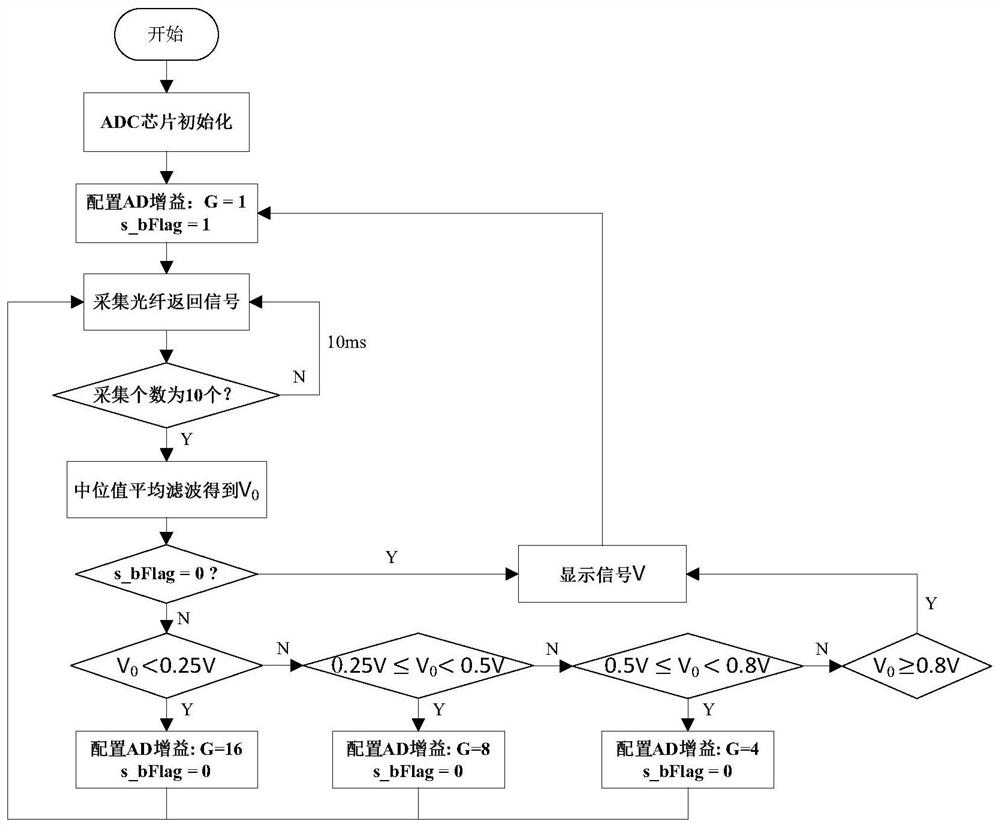
[0056] (2) Automatic gain adjustm...


PUM

PropertyMeasurementUnit
lengthaaaaaaaaaa
lengthaaaaaaaaaa

Abstract

The invention provides an interface detection method based on an optical interface detector; a closed-loop temperature control method is adopted, a constant-temperature environment is provided for a light-emitting device, the output light intensity of the light-emitting device is constant, the intensity of reflected light in different media is also constant, and thus when a system operates for a long time, the stability of a reflected light signal is good, and a good guarantee is provided for system interface detection; an automatic gain adjustment algorithm is adopted, the effect of an automatic amplification function of small signals is obvious during long-distance testing, and for signals with small difference, the output percentage of the signals with the small difference is increased by utilizing an output signal amplification principle, so that the signals with the small difference can also be obviously distinguished; and when the optical fiber length is 10 m and 2 km respectively, five media including water, 95# gasoline, 92# gasoline, 98# gasoline and 0# diesel oil can be accurately distinguished, the difference value between the 92# gasoline and the 98# gasoline reaches 20%, the test consistency is good, and the test data is stable.

Description

technical field [0001] The invention relates to a method for detecting an oil-mixed interface when oil products are sequentially transported in a refined oil pipeline, in particular to an interface detection method based on an optical interface detector. Background technique [0002] At present, in the transportation of refined oil, pipeline transportation has the advantages of high efficiency, low cost and less pollution, and has become the mainstream transportation method in the refined oil transportation industry. The pipeline transportation of refined oil generally adopts the sequential transportation method. During the transportation process, the two media freely diffuse, which will inevitably cause oil-contaminated sections. Accurate and timely detection of oil-contaminated sections plays an important role in the quality of refined oil. There are several existing oil-contaminated interface detection methods. One is to calculate the difference between the absorbance A1 ...

Claims


Application Information

Patent Timeline
Patent Type & Authority Applications(China)
IPC IPC(8): G01N21/55G01N13/00
CPCG01N21/55G01N13/00G01N2021/557Y02P90/02
Inventor 田中山董珊珊杨昌群井健王现中蔡婧牛道东杨露李育特徐中节
Owner PIPECHINA SOUTH CHINA CO
Why Eureka
Try Eureka