Device and method for monitoring rotating motor

A technology for rotating electrical machines and monitoring devices, which is applied in the direction of electromechanical devices, measuring devices, electronic commutation motor control, etc., and can solve the problems of undetectable, cost-increased, difficult real-time monitoring, etc.

Active Publication Date: 2012-06-27
TOSHIBA MITSUBISHI-ELECTRIC IND SYST CORP
View PDF3 Cites 0 Cited by
  • Summary
  • Abstract
  • Description
  • Claims
  • Application Information

AI Technical Summary

Problems solved by technology

[0009] In the method of estimating temperature from the resistance value of the coil, although the average temperature of the entire coil can be estimated, local temperature rise cannot be detected
[0010] In addition, according to the method of measuring temperature by installing a sensor such as a resistance temperature detector or a thermocouple near the coil, although a local temperature can be detected, the temperature measurement position is limited to a specific point, so the abnormally high temperature may occur in other positions. It is not possible to detect the condition
In order to increase the temperature measurement position, the number of sensors is required, and there is a problem of cost increase
[0011] In addition, in the method of detecting a partial discharge signal through a specific single-phase electrostatic coupling of the stator, or the method of detecting a pulse current signal through a high-frequency converter, the influence of external noise is large, and real-time monitoring is difficult.
[0012] In addition, in the method of extracting the gas in the casing of the rotating electric machine and analyzing it with a macroscopic analysis device, it is difficult to perform real-time monitoring.

Method used


Image

  • Device and method for monitoring rotating motor
  • Device and method for monitoring rotating motor
  • Device and method for monitoring rotating motor

Examples


Embodiment Construction

[0071] An embodiment of a rotating electric machine monitoring device and a monitoring method thereof according to the present invention will be described below with reference to the drawings.

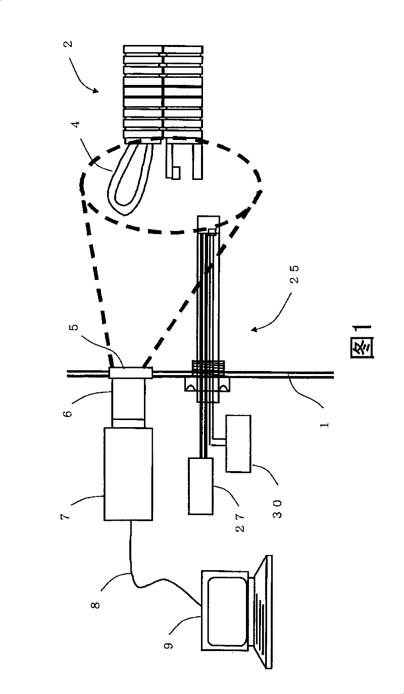
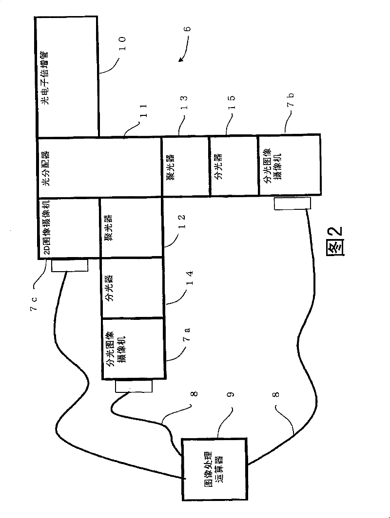
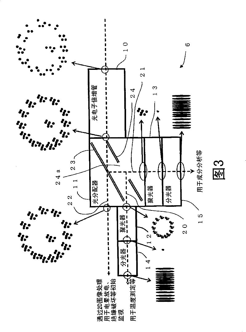
[0072] First, refer to Figure 1 to Figure 4 , and the configuration of the rotating electrical machine monitoring device according to this embodiment will be described. here, figure 1 It is a schematic vertical cross-sectional view showing the state in which the rotating electric machine monitoring device is installed on the rotating electric machine. in addition figure 2 It is a block diagram showing the configuration of the optical processing unit and its surroundings of the rotating electrical machine monitoring device. image 3 It is an explanatory diagram showing image data and the like on the optical processing unit and its surroundings. Figure 4 It is an enlarged longitudinal sectional view showing an auxiliary member heating device (attachment heater) in the rotating ele...


PUM


Abstract

The invention provides a rotating motor monitoring device, which is used for monitoring a rotating motor coved by a light-tight shell, and comprises: an observation window which is partially embedded in the shell and is light permeable but light-tight; a camera which is configured at the outer side of the observation window, receives radiant light generated on the inner side or transmitted by theobservation window and generates image data; and an arithmetic device which is used for processing image data. The arithmetic device is provided with a reference image data storage unit for saving the image data of black-body radiation in a reference state in the shell as referent image data, and a temperature computing unit for computing the temperature of the inside of the shell by comparing the image data and the reference image data.

Description

technical field [0001] The present invention relates to a device and method for monitoring the temperature and the like in a housing of a rotating electrical machine covered with a housing that does not transmit light. Background technique [0002] Conventionally, as a method of monitoring abnormality in the temperature of a coil of a rotating electrical machine such as a motor, a method of estimating the temperature from the resistance value of the coil is known. In addition, a method of measuring temperature by installing a sensor such as a resistance temperature detector or a thermocouple near the coil is also known. [0003] In addition, for diagnosing the state of insulation of a stator of a rotating electric machine, the magnitude and frequency of partial discharge pulses generated on the stator are evaluated. Therefore, a method of detecting a partial discharge signal through a specific single-phase electrostatic coupling and a method of detecting a signal of a pulsa...

Claims


Application Information

Patent Timeline
Patent Type & Authority Patents(China)
IPC IPC(8): G01J5/48H02K11/00G01N21/71G01J5/03
CPCG01J5/0893G01J5/08G01J5/0846H02K11/0047H02K11/001G01J5/0003G01J2005/0077G01J5/0096H02P6/00G01J5/60G01J5/061H02K11/20H02K11/25H02K11/00G01J5/48G01N21/71
Inventor 渡边刚八尾祐史
Owner TOSHIBA MITSUBISHI-ELECTRIC IND SYST CORP
Why Eureka
Try Eureka