Seabed automatic lobster catching cage

A technology of lobster and shrimp cages, which is applied in fishing, application, animal husbandry, etc., can solve the problems of increasing the difficulty of lobsters entering the cage, the anti-escape function is not ideal, and it is inconvenient for lobsters to enter at the same time, so as to improve the shrimp catching ability, The effect of preventing lobster from escaping and simple structure

Inactive Publication Date: 2009-09-02
湛江胜浪海洋捕捞研究所
View PDF0 Cites 9 Cited by
  • Summary
  • Abstract
  • Description
  • Claims
  • Application Information

AI Technical Summary

Problems solved by technology

[0002] The traditional lobster trap adopts a steel mesh structure. There is only one entrance in the cage body, which is not convenient for multiple lobsters to enter at the same time. The entrance size of the traditional trap is set very small to prevent the lobster from escaping. It is also difficult to escape, because there are two long spines in front of the lobster. The spines of the lobster are easy to be fenced outside the cage when the entrance is small, which increases the difficulty of the lobster entering the cage. It can be seen that this structure has a great impact on the catch. Big restrictions, because the entrance of the cage is set on the side of the cage and is not high from the seabed. According to the characteristics of the lobster: when the lobster finds that it is trapped, the lobster will walk around to find the exit, and when it finds the exit, it will try to escape, which can be seen to prevent escape The function is not ideal
In summary, the traditional lobster trap is a simple, unsatisfactory fishing ability and poor escape prevention ability to catch lobsters and fishing gear.

Method used


Image

  • Seabed automatic lobster catching cage
  • Seabed automatic lobster catching cage

Examples


Embodiment Construction

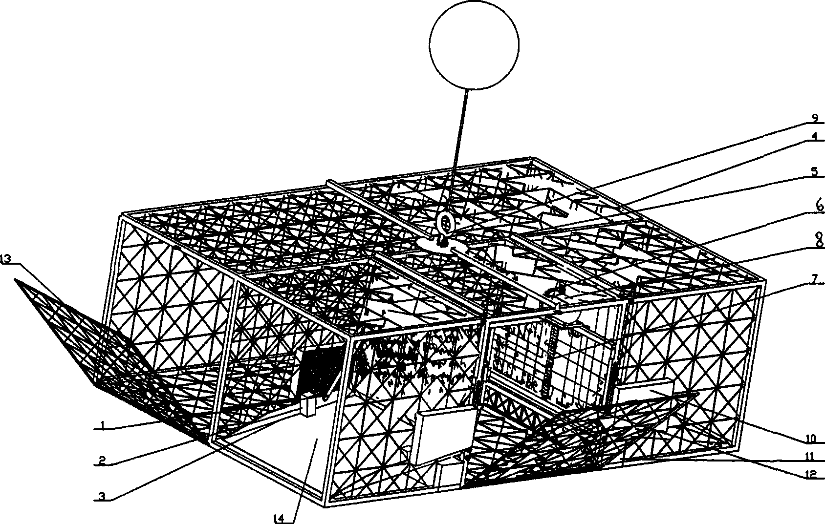
[0013] Such as figure 1 Shown, a kind of seabed automatic lobster trap includes shrimp pot 4, fishy lure box 10, lobster entrance 14 and forms, and fishy lure box 10 is located in the shrimp pot 4, and lobster entrance 14 is located at the two ends of shrimp pot 4, so The inner port of the lobster entrance 14 described above is provided with an electric lifting gate 5 and a gate lifting device, and the outside of the electric lifting gate 5 is provided with a shrimp bridge plate 3, and the shrimp bridge plate 3 is provided with a light control for controlling the lifting of the electric lifting gate. The switch 2, the connecting rod 1 is arranged between the shrimp bridge plate 3 and the electric lift gate 5, one end of the shrimp bridge plate 3 is hingedly connected with the shrimp cage 4, and the position near the other end of the shrimp bridge plate 3 is hingedly connected with the connecting rod 1, The other end of connecting rod 1 is hingedly connected with electric lifti...


PUM


Abstract

The invention discloses a seabed automatic lobster catching cage. The cage consists of a lobster cage, a temptation box and lobster inlets, wherein the temptation box is arranged in the lobster cage, the lobster inlets are arranged at both ends of the lobster cage, and inner ports of the lobster inlets are provided with escape-prevention electric lifting gates and gate lifting devices; a lobster bridge plate is provided with optical control switches for controlling the lifting of the electric lifting gates; connecting rods are arranged between the lobster bridge plate and the electric lifting gates; and one end of the lobster bridge plate is hinged with the lobster cage, the position close to the other end of the lobster bridge plate is hinged with the connecting rods, and the other ends of the connecting rods are hinged with the electric lifting gates. Because the lobster inlets of the cage body are provided with the wide inlets, the bridge plate and the electric escape-prevention gates, the lobsters can conveniently enter the cage, but hard to escape, thereby improving the capability of the catching cage in catching the lobsters. The catching cage has the advantages of high automaticity, suitability for commercial fishing and operation in any sea zones, strong fishing capability and effective prevention of the escape of the lobsters; moreover, the operation of placing the catching cage does not generate destructive influence on the oceanic ecology environment.

Description

technical field [0001] The invention relates to a mechanical device for marine lobster fishing, in particular to a function of using a light control switch to automatically control the cage bridge plate and the escape prevention gate to realize automatic operation. The setting of the automatic gate adds an escape prevention function to the trap. When the lobster trap is put into operation, the lobster comes to look for food under the action of the fishy lure box in the trap. When the lobster enters the bridge plate of the trap, the light control switch turns on the power of the motor to automatically turn the bridge plate upwards, and the anti-escape gate is linked. Open the bottom automatic lobster trap that forces the lobster into the cage to achieve the purpose of catching. Background technique [0002] The traditional lobster trap adopts a steel mesh structure. There is only one entrance in the cage body, which is not convenient for multiple lobsters to enter at the same...

Claims


Application Information

Patent Timeline
Patent Type & Authority Applications(China)
IPC IPC(8): A01K69/06
Inventor 谢永青
Owner 湛江胜浪海洋捕捞研究所
Why Eureka
Try Eureka