Hand-drying apparatus and hand-drying method

A hand dryer and sensor technology, which can be applied to household appliances and other directions, can solve the problems of high manufacturing cost, lack of practicability, and no cloth to wipe hands.

Inactive Publication Date: 2009-09-02
羊荣兴
View PDF2 Cites 6 Cited by
  • Summary
  • Abstract
  • Description
  • Claims
  • Application Information

AI Technical Summary

Problems solved by technology

Its shortcomings: first, the structure is complex and the manufacturing cost is high; second, it is impossible to realize the cycle drying, disinfection and use of the cloth in the cloth roll; third, because the length of the h...

Method used


Image

  • Hand-drying apparatus and hand-drying method
  • Hand-drying apparatus and hand-drying method
  • Hand-drying apparatus and hand-drying method

Examples


Embodiment 1

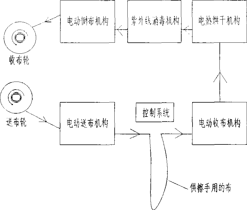
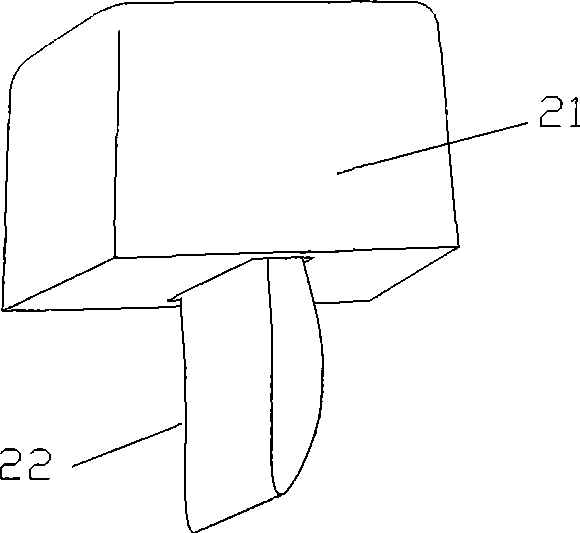
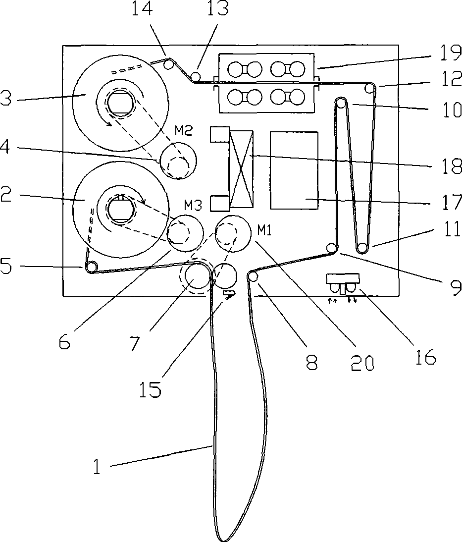
[0016] Embodiment 1: with reference to attached Figure 1~3 . Hand dryer 21, which includes a hand dryer shell and a control device, is composed of a cloth feeding wheel, a cloth feeding mechanism, a tensioning mechanism, an electric heating drying mechanism, a disinfection mechanism, a cloth reversing mechanism and a cloth receiving wheel. On the shaft, there is a cloth roll on it, and the cloth head in the cloth roll is connected with the cloth take-up wheel. The cloth feeding mechanism and the tensioning mechanism are respectively located on both sides of the lower cloth opening of the hand dryer shell, and the electric heating drying mechanism is located on the side of the tensioning mechanism. And the hot air directly blows the cloth surface (the electric heating drying mechanism is made of electric heating wire 17 and fan 18, and the electric heating wire 17 is positioned at the air outlet of fan 18, or the electric heating drying mechanism adopts hot air blower to dry)....

Embodiment 2

[0017] Embodiment 2: On the basis of Embodiment 1, the hand drying method of the hand dryer, before use, the cloth feeding motor 20 drives the counter-pressing cloth feeding roller 7 to rotate, and the counter-pressing cloth feeding roller 7 passes the clean cloth through the guide roller 5 Guide and send the cloth 22 in the cloth roll on the cloth feeding wheel 2 to the lower part of the hand dryer. When the hand reaches the bottom of the hand dryer, the sensor 16 is used to get a signal, and the control device confirms that the hand dryer is in use. In the process, when the signal of the sensor 16 disappears after the person wipes his hands and leaves the hand dryer, the control device receives the signal transmitted by the sensor 16 and instructs the cloth receiving motor 4 to drive the cloth receiving wheel 3 to rotate, and the used wet cloth passes through the guide. Roller 8 and the S-shaped tensioning mechanism tension the cloth surface. At this time, the electric heatin...

Embodiment 3

[0018] Embodiment 3: On the basis of Embodiment 1 or 2, when the hand dryer is not in use, the cloth rewinding motor 6 drives the cloth feeding wheel 2 to rotate, and the cloth belt is rolled back from the cloth receiving wheel 3 to the cloth feeding wheel 2 , the wet cloth sent back from the cloth receiving wheel passes through the ultraviolet disinfection lamp 19 for sterilization and disinfection on both sides, and then enters the S-shaped cloth composed of the upper tension roller 10, the upper tension roller 12, the lower tension roller 9, and the lower tension roller 11. With a drying area, the fan 18 blows the wind over the surface of the heating wire 17, the hot air dries the wet cloth, and the cloth rewinding motor 6 rewinds the sterilized and dried clean cloth to the cloth feeding wheel to realize recycling.


PUM


Abstract

The invention relates to a hand-drying apparatus and a hand-drying method used for hand-drying; before use, a cloth-sending motor drives an opposite-pressure cloth-sending roller to rotate so as to send clean cloth to the position below the dropping port of the hand-drying apparatus, when hands extend below the hand-drying apparatus, a use sensor obtains a signal, and a control device confirms that the hand-drying apparatus is in use; when the hands leave the hand-drying apparatus after drying, the signal of the use sensor disappears, the control device receives the signal transmitted by the use sensor, an instruction cloth-folding motor drives a cloth-folding wheel to rotate, the used wet cloth tenses or stretches the cloth belt surface by a guide roller and an S-shaped tensing mechanism, and an electric heating drying mechanism dries the cloth surface; when the dried cloth belt passes through a sterilizing mechanism, sterilizers positioned on the upper surface and the lower surface of the cloth sterilize the two surfaces of the cloth simultaneously, the sterilized cloth is coiled on the cloth-folding wheel by a compressing mechanism; and when a cloth-folding sensor senses a signal of cloth-folding, the control device receives the signal transmitted by the cloth-folding sensor, the instruction cloth-folding motor stops rotating, and the cloth-folding process is finished.

Description

technical field [0001] The invention relates to a hand dryer and a hand drying method for drying hands, belonging to the field of hand dryer manufacturing. Background technique [0002] CN2666335Y, name "hand dryer", the hand dryer includes a bottom plate, a cover plate and a side plate, the bottom plate is movably connected to the cover plate through a connecting rod, the two sides of the bottom plate are connected with the side plate, the sliding shaft, the gear transmission shaft, the transmission gear The gear follower shaft and the reel are connected to the side plate, the gear transmission shaft is located between the sliding shaft and the transmission gear, the transmission gear is located between the gear transmission shaft and the gear follower shaft, and the gear follower shaft is located between the transmission gear and the reel, The cloth roll is positioned in the groove at the lower end of the base plate, and the hand towel on the cloth roll passes between the ...

Claims


Application Information

Patent Timeline
IPC IPC(8): A47K10/30A47K10/26
Inventor 羊荣兴
Owner 羊荣兴
Why Eureka
Try Eureka