
Closed compressor and refrigerating circulation device

A compressor and hermetic technology, applied in the direction of compressors, irreversible cycle compressors, refrigerators, etc., can solve the problem of insufficient lubricating oil in the second cylinder chamber, to eliminate insufficient lubricating oil, ensure increased resistance, and improve reliability sexual effect

Inactive Publication Date: 2012-07-11
TOSHIBA CARRIER CORP
View PDF1 Cites 0 Cited by
  • Summary
  • Abstract
  • Description
  • Claims
  • Application Information

AI Technical Summary

Problems solved by technology

Therefore, when running at full capacity again, it may happen that the lubricant in the second cylinder chamber is insufficient

Method used


Image

  • Closed compressor and refrigerating circulation device
  • Closed compressor and refrigerating circulation device
  • Closed compressor and refrigerating circulation device

Examples


no. 1 approach

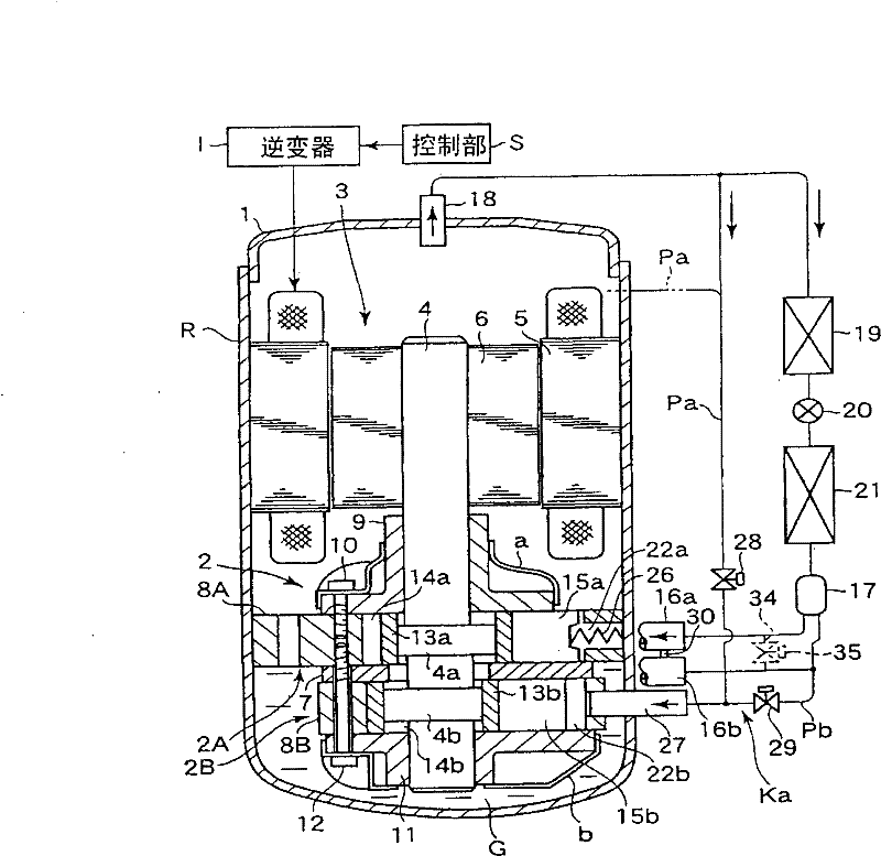
[0043] figure 1 It is a diagram showing a cross-sectional structure of a hermetic rotary compressor R and a configuration of a refrigeration cycle including the hermetic rotary compressor R.

[0044] First, the hermetic rotary compressor R will be described. Reference numeral 1 denotes a hermetic casing. A compression mechanism 2 , which will be described later, is provided in the lower portion of the hermetic casing 1 , and a motor unit 3 is provided in the upper portion. The motor unit 3 and the compression mechanism unit 2 are connected by a shaft 4 . An oil reservoir G for storing lubricating oil is formed on the inner bottom of the airtight case 1, and the compression mechanism unit 2 is almost completely immersed in the lubricating oil.

[0045] The motor unit 3 includes: a stator 5 fixed to the inner surface of the airtight casing 1; and a rotor 6 disposed inside the stator 5 with a predetermined gap and inserted with the rotating shaft 4 . The motor unit 3 is connect...


PUM


Abstract

The present invention provides a closed compressor and a refrigerating circulation device including the same, which can prevent the increase of the resistance of suction passage of cutting-out cylindeThe present invention provides a closed compressor and a refrigerating circulation device including the same, which can prevent the increase of the resistance of suction passage of cutting-out cylinder side when full operation to ensure energy saving, and eliminate the deficiency of lubricating oil to increase the reliability. In the multiple compressor components of the closed compressor, the secr side when full operation to ensure energy saving, and eliminate the deficiency of lubricating oil to increase the reliability. In the multiple compressor components of the closed compressor, the second compressor component (2B) comprises a first cutting-out cylinder mechanism (Ka) which guides the low pressure freezing medium gas in the storage tank (17) to the cylinder (14b) via the suction tubond compressor component (2B) comprises a first cutting-out cylinder mechanism (Ka) which guides the low pressure freezing medium gas in the storage tank (17) to the cylinder (14b) via the suction tube (16b), applies low pressure back pressure to the rear end portion of the blade (15b) of the cylinder to eliminate the difference pressure of the front end portion and the rear end portion of the blae (16b), applies low pressure back pressure to the rear end portion of the blade (15b) of the cylinder to eliminate the difference pressure of the front end portion and the rear end portion of the blade, such that the front end portion of the blade deviates from the drum (13b), thus realizing the cutting-out cylinder running for stopping the compression running of the cylinder, at the downstream ode, such that the front end portion of the blade deviates from the drum (13b), thus realizing the cutting-out cylinder running for stopping the compression running of the cylinder, at the downstream of the storage tank, a communicating passage (30) for communicating the suction pipes of a second compressor component for cutting-out cylinder running and a first compressor component (2A) not for cutf the storage tank, a communicating passage (30) for communicating the suction pipes of a second compressor component for cutting-out cylinder running and a first compressor component (2A) not for cutting-out cylinder running is arranged.ting-out cylinder running is arranged.

Description

technical field [0001] The present invention relates to, for example, a hermetic compressor constituting a refrigerating cycle of an air conditioner, and a refrigerating cycle device constituting a refrigerating cycle using the hermetic compressor. Background technique [0002] In recent years, a two-cylinder rotary hermetic compressor consisting of two sets of cylinders upper and lower is being standardized. Furthermore, in such a compressor, it is advantageous to include a cylinder that always performs a compression function and a cylinder that can be switched between compression and stop as needed, so that the operation can be performed according to the load, and the specifications can be increased. [0003] The present applicant provides the above-mentioned hermetic compressor in Patent Document 1. In such a hermetic compressor, during normal full-capacity operation, low-pressure refrigerant gas is introduced into the first cylinder chamber, the drum is rotated to compr...

Claims


Application Information

Patent Timeline
Patent Type & Authority Patents(China)
IPC IPC(8): F04C18/32F25B1/04
Inventor 小野田泉
Owner TOSHIBA CARRIER CORP
Learn More