Condensate draining pipe and method for assembling a condensate draining pipe

A technology for condensate and drain pipes, which can be used in condensate prevention, transportation and packaging, heating/cooling equipment, etc., and can solve problems such as complicated condensate drain hoses

Inactive Publication Date: 2009-09-02
GM GLOBAL TECH OPERATIONS LLC
View PDF1 Cites 14 Cited by
  • Summary
  • Abstract
  • Description
  • Claims
  • Application Information

AI Technical Summary

Problems solved by technology

However, the disadvantage is that such a monolithic condensate drain hose is complicated to fit into the vehicle

Method used


Image

  • Condensate draining pipe and method for assembling a condensate draining pipe
  • Condensate draining pipe and method for assembling a condensate draining pipe
  • Condensate draining pipe and method for assembling a condensate draining pipe

Examples


Embodiment Construction

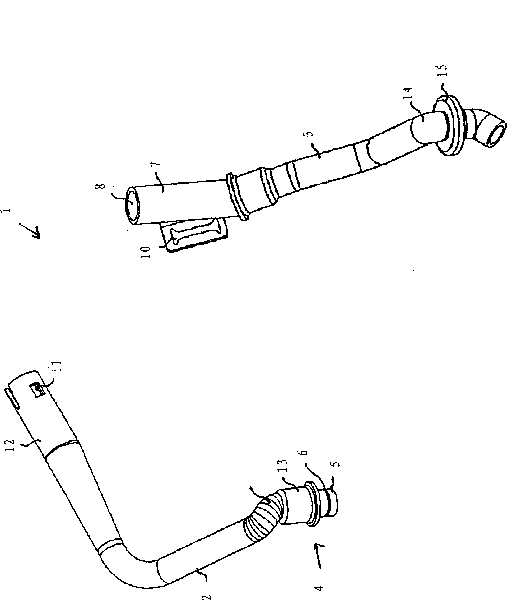
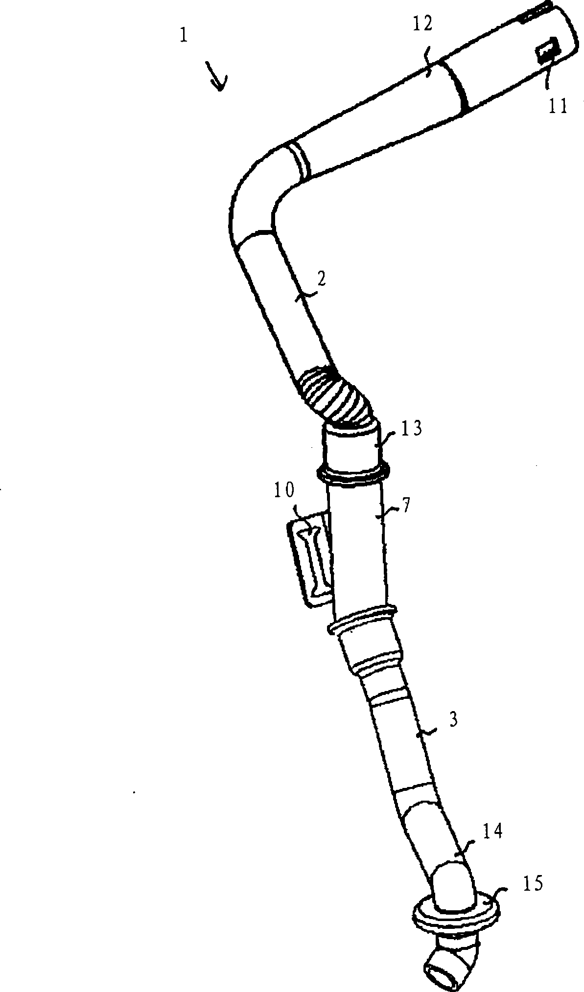
[0076] figure 1 and 2 Components of a condensate drain pipe 1 of an automotive heating, ventilation and / or air conditioning (HVAC) system according to a first embodiment of the invention are shown. figure 1 Each component is shown unassembled, figure 2 for the assembled components.

[0077] The condensate drain 1 comprises two separate fittings, the condensate supply 2 and the condensate drain 3 each having a generally tubular shape. The condensed water supply part 2 and the condensed water drain part 3 can be connected to each other through a coupling device 4 to form a condensed water drain pipe 1 .

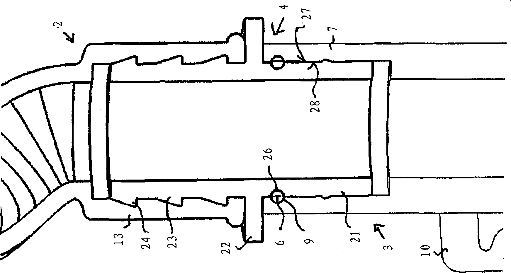
[0078] The coupling device 4 forms a press-fit joint enabling the detachable interconnection of the two separate parts 2 and 3 of the condensate drain pipe 1 . The coupling device 4 comprises a shaft fitting 5 , an O-ring seal 6 and a sleeve flange fitting 7 , which are shown in more detail in FIG. 3 .

[0079] The shaft fitting 5 is in the shape of a tubular nozzle which...


PUM


Abstract

A condensate draining pipe (1) for a heating, ventilating and / or air conditioning (HVAC) system comprises a condensate feed portion (2) and a condensate drain portion (3). The condensate feed portion (2) and the condensate drain portion (3) are connectable to one another by a press-fit coupling assembly (4) comprising an O-ring seal (6).

Description

technical field [0001] The present invention relates to a condensate drain of a heating, ventilation and / or air conditioning (HVAC) system, for example of an automobile, and to a method of assembling a condensate drain of an HVAC system. Background technique [0002] Heating, ventilation and / or air conditioning systems, such as those of automobiles, typically include a drain pan located under the evaporator for collecting condensation that forms on the evaporator when the system is in operation. The condensed water collected in the drain pan is drained via a condensate drain hose extending from the water pan to a drain hole provided, for example, on the vehicle floor in contact with the outside. [0003] From EP1645447B1 is known a condensate drain hose for a vehicle air-conditioning system, comprising a rigid part penetrating through the wall of the vehicle, and a co-molded elastic part whose end can be connected to the water pan of the air-conditioning system. However, su...

Claims


Application Information

Patent Timeline
IPC IPC(8): F24F13/22B60H1/32
CPCB60H1/3233B60H1/00557Y10T29/49908Y10T29/49826
Inventor 奥拉夫·卡登安德烈亚斯·马勒奇克
Owner GM GLOBAL TECH OPERATIONS LLC
Why Eureka
Try Eureka