Earphone

A technology of earphones and wires, applied in the field of audio equipment, can solve the problems of asynchronous transmission of high-pitched, mid-range and low-frequency earphones, destroying the full-band playback effect of earphone sound, and unsatisfactory sound quality of earphones, so as to overcome the problems of full-band playback. Poor, overcoming the inability to filter out harmonics in time, ensuring the effect of full-band playback

Active Publication Date: 2009-09-02
赵明慧 +1
View PDF0 Cites 0 Cited by
  • Summary
  • Abstract
  • Description
  • Claims
  • Application Information

AI Technical Summary

Problems solved by technology

[0004] The problem existing in the existing earphones is that the audio signal processed by the amplifier circuit contains a large number of harmonics, which are returned to the amplifier circuit after being transmitted by the voice coil wire and accumulated continuously, which eventually leads to the unsatisfactory sound quality of the sound reproduced by the earphone.
[0005] In addition, when the diaphragm is pushed by the voice coil to vibrate, part of the energy is transmitted from the center of the diaphragm to the edge of the earphone, and this part of the energy is blocked by the edge and returns to the center of the diaphragm, resulting in transmission from the center of the diaphragm to the edge of the earphone. The energy of the earphone interferes, causing feedback distortion; and, due to the different frequencies of the treble, midrange, and bass transmitted through the earphones, the treble, midrange, and bass transmissions of the earphones are not synchronized, thereby destroying the full-band playback effect of the earphones.

Method used


Image

  • Earphone
  • Earphone
  • Earphone

Examples


Embodiment Construction

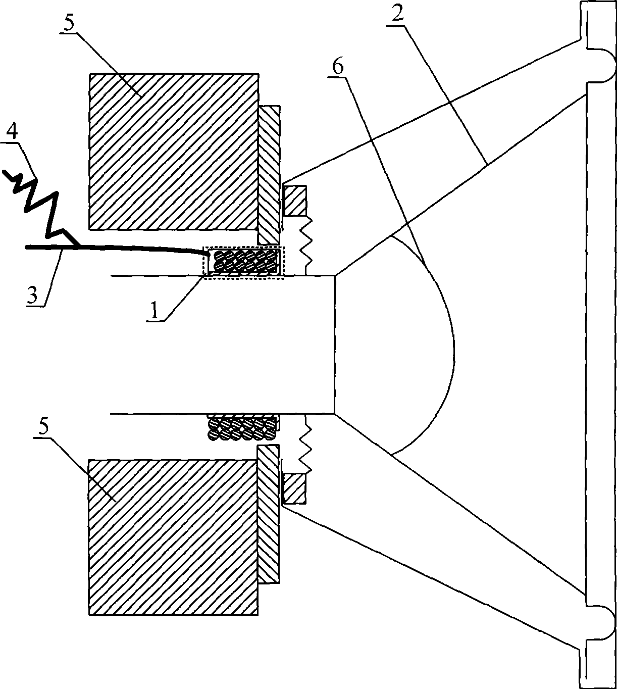
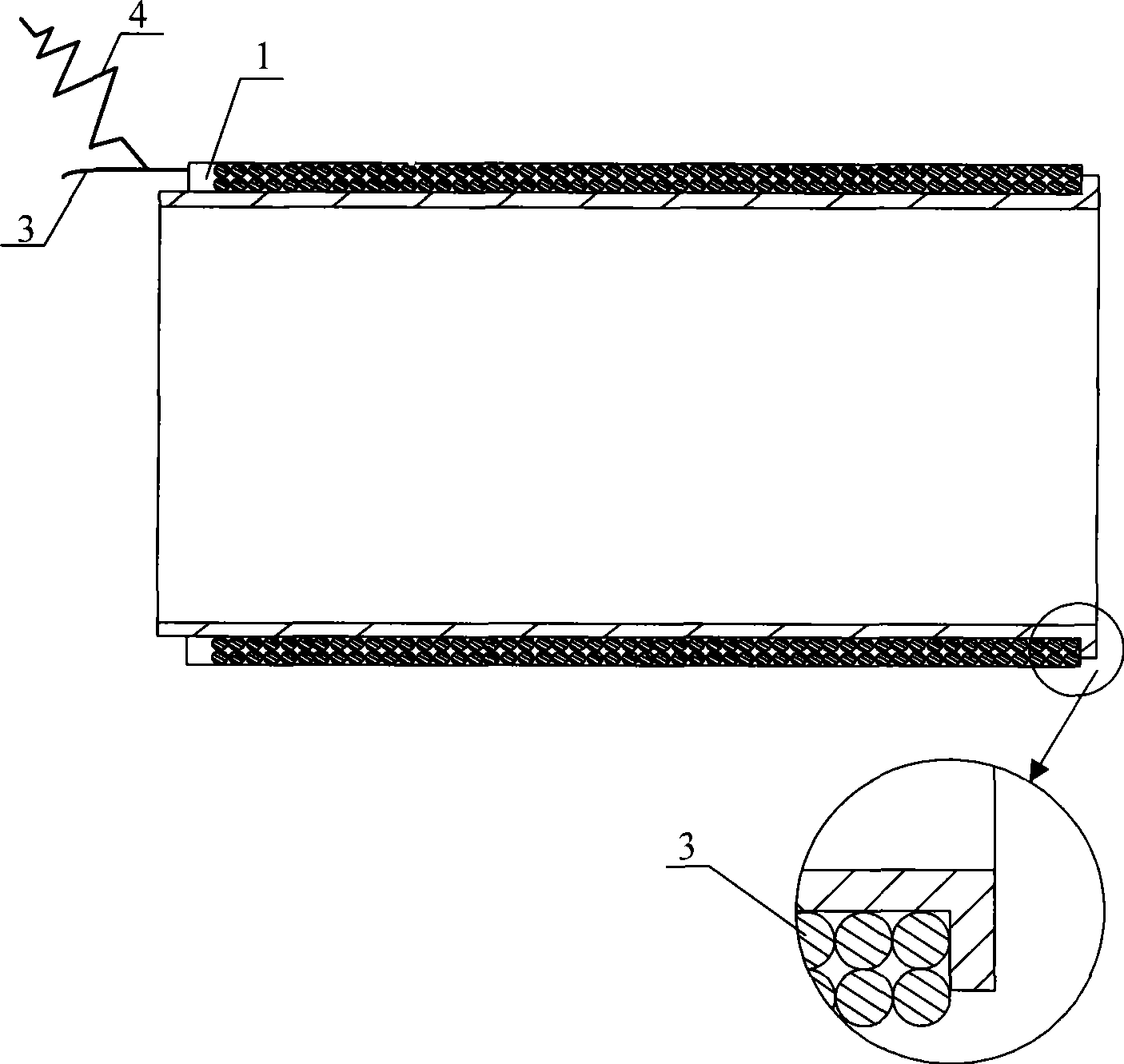
[0025] figure 1 It is a structural schematic diagram of an earphone embodiment of the present invention, such as figure 1 As shown, the voice coil 1 includes a diaphragm 2 and a voice coil wire wound. In this embodiment, the diaphragm 2 adopts a cone-shaped diaphragm. The diaphragm 2 is fixed together with the voice coil 1 . The voice coil 1 is composed of voice coil wires 3 . further, figure 2 It is a structural schematic diagram of the voice coil in the earphone embodiment of the present invention, as figure 2 As shown, the electrical signal output end of the voice coil wire 3 is not only connected to the amplifier circuit for processing audio signals, but also connected to a wire 4, one end of the wire 4 is suspended, and the cross section of the wire 4 is circular.

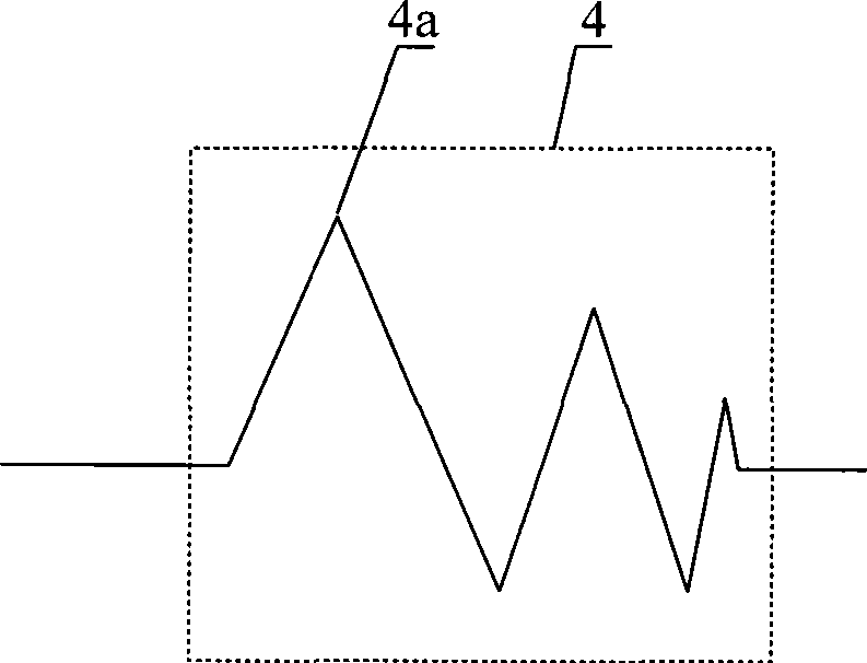
[0026] further, image 3 It is a structural schematic diagram of the first embodiment of the wire in the earphone embodiment of the present invention, Figure 4 It is a schematic structural diagram of ...


PUM


Abstract

The invention relates to an earphone, comprising a voice coil, a vibrating diaphragm and a dustproof cover; wherein the voice coil is wound by voice coil wires; the output end of the voice coil wire is connected with a wire; one end of the wire hangs in the air; the wire comprises a bending segment which consists of a folded line unit and/or a bent line unit in the same plane; and the range of the bent line is gradually descended. The folded line unit is formed by straight wires in a certain angle; the bent line unit is formed by bent wires in a certain radian; the width between the straight wires of the folded line unit and/or the width between the bent wires of the bent line unit are gradually descended from the output end of the voice coil wire to the wire hanging end containing the bent line. The wire eliminates harmonic waves and ensures the acoustics of the regenerated sound of the earphone. Furthermore, the projection of the dustproof cover on the bottom of the vibrating diaphragm is positioned in a triangular that is formed by the projection of a first through hole of alt register, a second through hole of a mediant register and a third through hole of a bourdon register arranged on the vibrating diaphragm in a plane where the bottom of the vibrating film is positioned; the earphone overcomes asynchronous transmission of alt, mediant and bourdon and ensures the full frequency of the earphone sound with playback effect.

Description

technical field [0001] The invention relates to audio equipment, in particular to an earphone capable of optimizing the sound quality of reproduced sound. Background technique [0002] With the development of science and technology and people's pursuit of high-quality life, earphones have become indispensable in people's lives, such as earphones used in audio-visual equipment such as MP3 and MP4, and mobile communication devices such as mobile phones and handheld computers. [0003] At present, the earphone mainly includes a voice coil and a diaphragm, and the voice coil and the diaphragm are fixed together; the bottom of the diaphragm is provided with a dust cover. The earphone also includes a permanent magnet. The changing audio signal makes the voice coil cut the magnetic force line in the magnetic field formed by the permanent magnet. The force on the voice coil changes with the change of the audio signal and is transmitted to the diaphragm fixed with the voice coil. , ...

Claims


Application Information

Patent Timeline
Patent Type & Authority Applications(China)
IPC IPC(8): H04R1/10
CPCY02T10/7005
Inventor 毕征庆
Owner 赵明慧
Why Eureka
Try Eureka