Electrical cabinet remote monitoring system based on Internet of things

A technology of remote monitoring system and electrical cabinet, applied in the field of signal transmission, can solve the problems of data loss of data information, inaccurate data signal of electrical cabinet, distortion of carrier signal, etc.

Inactive Publication Date: 2020-06-05
李韬
View PDF5 Cites 0 Cited by
  • Summary
  • Abstract
  • Description
  • Claims
  • Application Information

AI Technical Summary

Problems solved by technology

[0002] At present, many remote monitoring systems for electrical cabinets currently use carrier transmission. Due to the long-distance transmission, they often encounter the interference of equal or high-frequency signals in the atmospheric environment, such as power plants and signal towers. The carrier signal is often distorted, resulting in all The modulated data information will lose part of the data, resulting in inaccurate data signals of the electrical cabinet and reducing the use effect of the remote monitoring system of the electrical cabinet

Method used


Image

  • Electrical cabinet remote monitoring system based on Internet of things
  • Electrical cabinet remote monitoring system based on Internet of things
  • Electrical cabinet remote monitoring system based on Internet of things

Examples


Embodiment 1

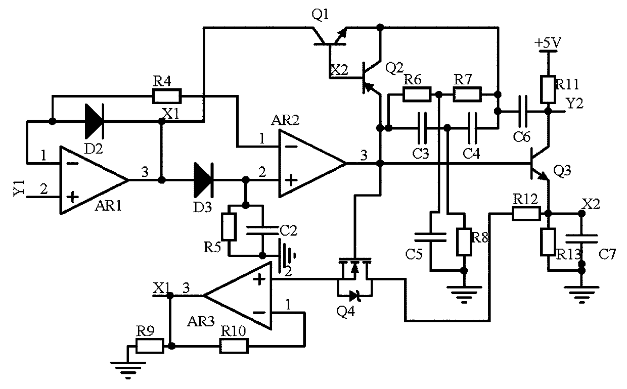
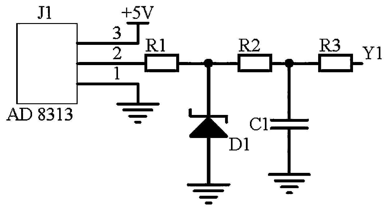
[0012] Embodiment 1, a remote monitoring system for electrical cabinets based on the Internet of Things, including a waveform detection module, a frequency modulation feedback module and a limiter transmission module, the waveform detection module uses a detector J1 model AD 8313 to collect signals when the electrical cabinet is working The transmitter outputs the carrier signal waveform, and the FM feedback module uses the operational amplifier AR1, the operational amplifier AR2, the diode D2, and the diode D3 to form a detection circuit to screen out the peak signal, and then uses the resistor R6-resistor R8 and capacitor C3-capacitor C7 to form The frequency modulation circuit adjusts the signal frequency, and uses the thyristor Q4 and the op amp AR3 to feed back the emitter signal of the transistor Q3 to the output of the op amp AR1, adjusts the output signal potential of the peak circuit, and uses the triode Q1 and the triode Q1 to form a switch circuit to detect the peak v...

Embodiment 2

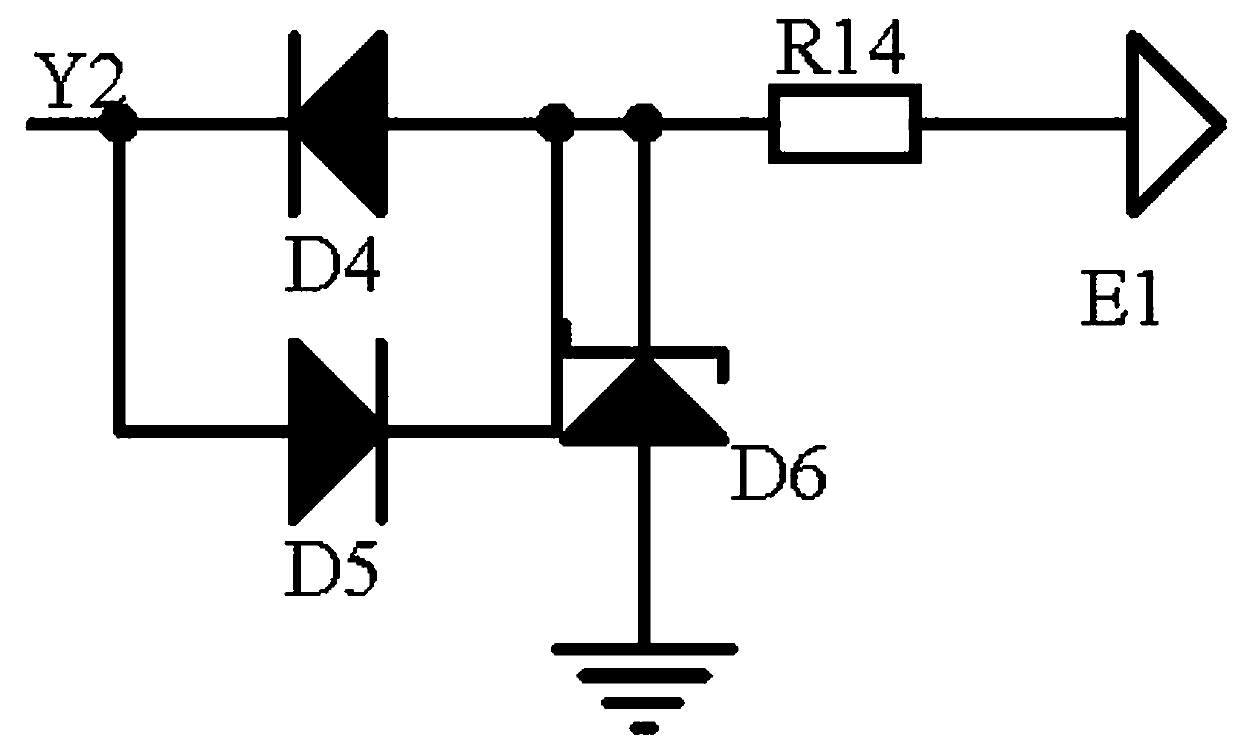
[0015] Embodiment 2. On the basis of Embodiment 1, the limiting transmission module uses diode D4 and diode D5 to form a limiting circuit to limit the signal, and send it to the remote monitoring terminal of the electrical cabinet through the signal transmitter E1, so as to facilitate timely filtering. In addition to the wrong data signal transmitted by the carrier signal, the data signal can be received again in time. The cathode of the diode D4 is connected to the anode of the diode D5 and the collector of the transistor Q3. The anode of the diode D4 is connected to the cathode of the diode D5, one end of the resistor R14 and the stable The negative pole of the pressure tube D6, the positive pole of the regulator tube D6 are grounded, and the other end of the resistor R14 is connected to the signal transmitter E1;

[0016] The waveform detection module selects the wave detector J1 of model AD 8313 to collect the signal transmitter output carrier signal waveform when the elect...


PUM


Abstract

The invention discloses an electrical cabinet remote monitoring system based on the Internet of things. The system comprises a waveform detection module, a frequency modulation feedback module and anamplitude limiting transmitting module. The waveform detection module uses a detector J1 with the model of AD 8313 to collect carrier signal waveforms output by a signal emitter when an electrical cabinet works. The frequency modulation feedback module uses an operational amplifier AR1, an operational amplifier AR2, a diode D2 and a diode D3 to form a detection circuit to screen out peak signals,uses resistors R6-R8 and capacitors C3-C7 to form a frequency modulation circuit to adjust the signal frequency, and uses a silicon controlled rectifier Q4 and an operational amplifier AR3 to feed back an emitter signal of a triode Q3 to the output end of the operational amplifier AR1 to adjust the potential of the output signal of a peak value circuit. Finally, the amplitude limiting transmittingmodule uses a diode D4 and a diode D5 to form an amplitude limiting circuit to limit the amplitude of the signal, and the signal is transmitted to an electrical cabinet remote monitoring terminal through a signal transmitter E1. The waveform of a carrier signal output by the signal transmitter when the electrical cabinet works can be calibrated and converted into an error reference signal of theelectrical cabinet remote monitoring terminal.

Description

technical field [0001] The invention relates to the technical field of signal transmission, in particular to an electrical cabinet remote monitoring system based on the Internet of Things. Background technique [0002] At present, many remote monitoring systems for electrical cabinets currently use carrier transmission. Because of the long-distance transmission, they often encounter the interference of equal or high-frequency signals in the atmospheric environment, such as power plants and signal towers. The carrier signal is often distorted, resulting in all The modulated data information will lose part of the data, resulting in inaccurate data signals of the electrical cabinet and reducing the use effect of the remote monitoring system of the electrical cabinet. Contents of the invention [0003] In view of the above situation, in order to overcome the defects of the prior art, the purpose of the present invention is to provide a remote monitoring system for electrical c...

Claims


Application Information

Patent Timeline
Patent Type & Authority Applications(China)
IPC IPC(8): H03F1/32H03F3/189
CPCH03F1/32H03F3/189
Inventor 李韬
Owner 李韬
Why Eureka
Try Eureka