Eureka AIR delivers breakthrough ideas for toughest innovation challenges, trusted by R&D personnel around the world.

Aerosol aspirator, and its sucking method

An aspirator, aerosol technology, applied in the field of aerosol aspirator, can solve the problem of not being able to attract aerosol and so on

Active Publication Date: 2009-09-02
JAPAN TOBACCO INC
View PDF1 Cites 29 Cited by
  • Summary
  • Abstract
  • Description
  • Claims
  • Application Information

AI Technical Summary

Problems solved by technology

Therefore, the user cannot inhale a fixed amount of aerosol every time he inhales.

Method used


Image

  • Aerosol aspirator, and its sucking method
  • Aerosol aspirator, and its sucking method
  • Aerosol aspirator, and its sucking method

Examples


Embodiment Construction

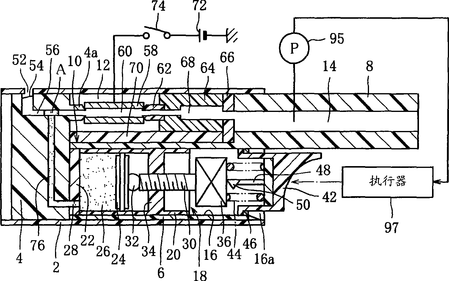
[0034] figure 1 It is a figure which shows the aerosol aspirator of 1st Example.

[0035] figure 1 The aspirator of the present invention has a housing 2 which is in the shape of a hollow cylinder with openings at both ends. An open end of the housing 2 is closed by an end wall 4 . A cylinder block 6 is embedded in the casing 2 , and a bottom of the cylinder block 6 abuts against the end wall 4 is provided at one end, and a tubular suction nozzle 8 is integrally provided at the other end. The suction nozzle 8 protrudes from the other open end of the housing 2 .

[0036] The cylinder block 6 has on its outer peripheral surface a depression 10 which extends from the bottom of the cylinder block 6 to the suction nozzle 8 . The recess 10 and the inner peripheral surface of the housing 2 jointly define a heating chamber 12 which communicates with an internal passage 14 of the suction nozzle 8 .

[0037] Furthermore, a cylinder bore 16 is formed in the cylinder block 6 . The c...


PUM


Abstract

The present invention relates to an aerosol aspirator and its sucking methods, wherein the aerosol aspirator has a casing (2) with a mouthpiece (8) and an outside air inlet (52), a generation passage (56, 60, 68) extending from the outside air inlet (52) to the mouthpiece (8), a syringe pump (18) arranged within the casing (2) to deliver a solution to a distributing position (A) in the generationpassage in a fixed amount each time it is activated, and a tubular heater (58) disposed downstream of the distributing position (A) and forming a part of the generation passage. When a user sucks at the mouthpiece (8), the solution at the distributing position (A) is transferred from the position (A) into the heater (58), and within the heater, atomized, and then turns into an aerosol by condensing in sucked air flow, and the aerosol thus formed is sucked by the user with the air flow.

Description

technical field [0001] The present invention relates to an aerosol inhaler and its inhalation method for supplying medicines or luxury items to users in the form of aerosol. Background technique [0002] Such an aerosol aspirator is disclosed in Patent Document 1, for example. The aspirator of this patent document 1 has: a supply device for supplying a substance in liquid form, a capillary tube which is filled with the substance supplied from the supply device and has an opening at its front end, and a suction nozzle (moussupus) provided adjacent to the front end opening of the capillary tube. . A heater disposed so as to surround the tip of the capillary. The heater heats and vaporizes the substance in the capillary, and the substance in vapor form is ejected from the front end opening of the capillary by itself. [0003] In this case, when the user inhales through the mouthpiece, the substance in the form of vapor condenses upon contact with the suction air and becomes a...

Claims


Application Information

Patent Timeline
IPC IPC(8): A61M15/00A61M11/00A61M11/02B05B17/04B05B7/24
CPCA61M2016/0027A61M11/007A61M11/041A61M15/0085A61M2202/04A61M11/005A61M15/00A61M15/008A61M11/00A61M15/06B05B17/04A61M15/0091
Inventor 山田学佐佐木宏片山和彦矢岛盛雄
Owner JAPAN TOBACCO INC
Why Eureka
Eureka Blog
Learn More