Realtime spectrum trigger system on realtime oscilloscope

一种滤波器、发生器的技术,应用在仪器、数字变量显示、数字变量/波形显示等方向,能够解决未考虑相位谱等问题

Inactive Publication Date: 2009-09-02
TEKTRONIX INC
View PDF0 Cites 9 Cited by
  • Summary
  • Abstract
  • Description
  • Claims
  • Application Information

AI Technical Summary

Problems solved by technology

However, only the magnitude spectrum is considered, and the phase spectrum is not considered

Method used


Image

  • Realtime spectrum trigger system on realtime oscilloscope
  • Realtime spectrum trigger system on realtime oscilloscope
  • Realtime spectrum trigger system on realtime oscilloscope

Examples


Embodiment Construction

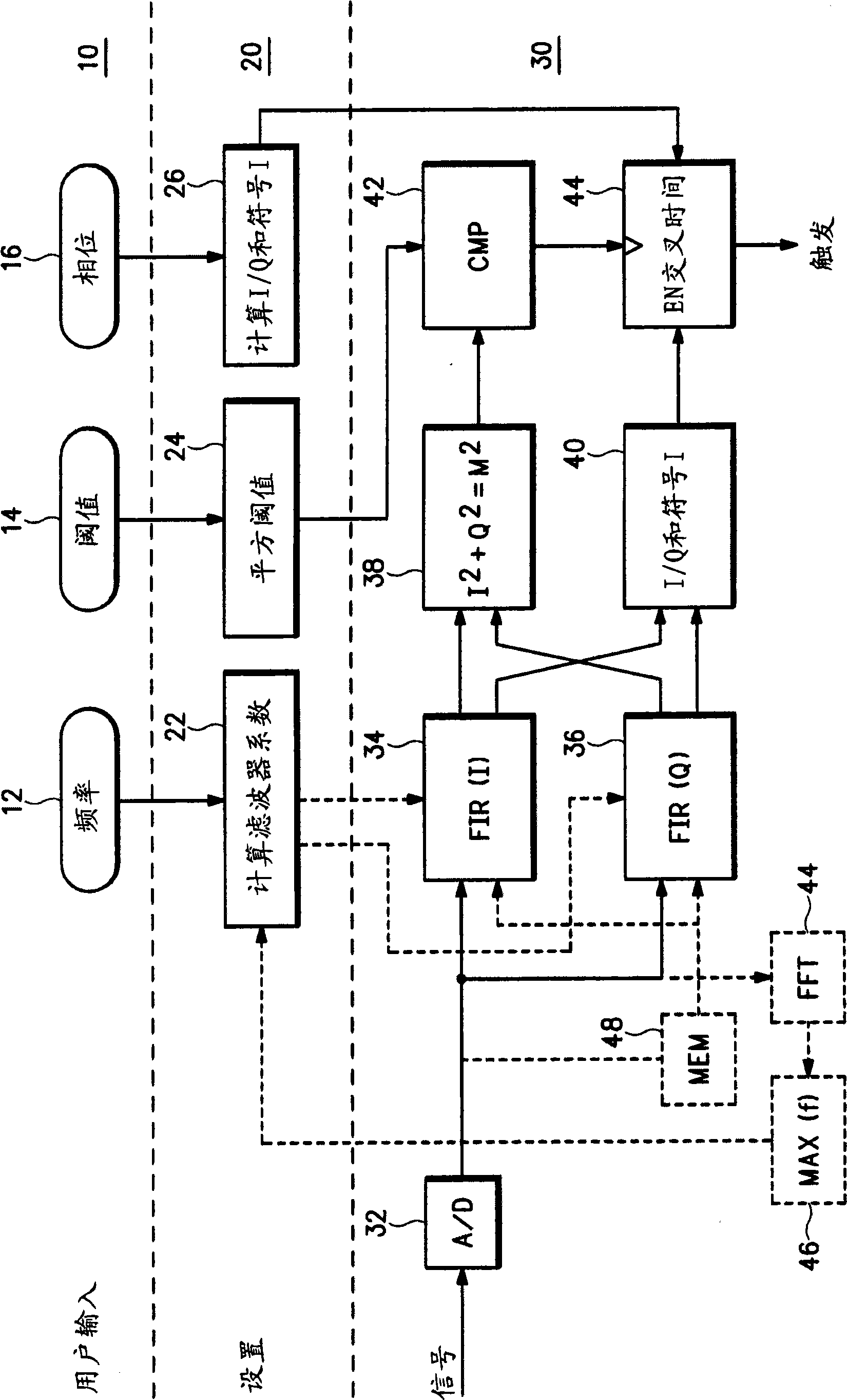
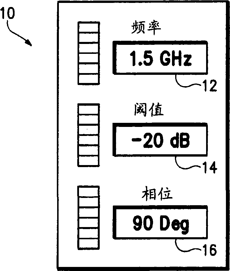
[0014] now refer to figure 2 , a real-time spectrum trigger system on a real-time oscilloscope with features such as image 3 A user input portion 10 of the user interface is shown where the user may enter a desired trigger frequency 12, an amplitude threshold at the trigger frequency 14, and a phase crossing 16 at the trigger frequency. Based on user input, setup section 20 calculates filter parameters 22 from user-selected frequencies, square thresholds 24 from user-input magnitude thresholds, and quadrature I / Q ratios and quadrature I / Q ratios from user-selected phase crossings. Sign of the I component. In the setup section 20, the real-time oscilloscope performs several calculations and then uses the results of said calculations in the oscilloscope hardware. A discrete Fourier transform (DFT) is performed to obtain the spectrum at the desired trigger frequency.

[0015] (DFT)X(k)=∑ m=0-(N-1) ×(m)W N km =W N -kN ∑ m=0-(N-1) ×(m)W N km =∑ m=0-(N-1) ×(m)W N -k(...


PUM


Abstract

A realtime spectrum trigger system on a realtime oscilloscope considers both the magnitude and phase (38,40) of an input signal having a periodic component so that successive acquisitions of the input signal are time aligned. A user inputs a frequency, threshold and phase for triggering on the periodic component. Input signal samples are filtered by quadrature filters (34,36) according to the frequency input to produce quadrature signal components. The square of the magnitude of the input signal is computed (38) from the quadrature signal components, as well as the phase ratio and sign (40), for comparison with calculated values. When enabled by the magnitude of the input signal, a phase crossing determinator (44) compares the phase ratio and sign with calculated values to determine the phase crossing to generate a trigger, resulting in successive acquisitions of the input signal being in time alignment.

Description

technical field [0001] The present invention relates to an oscilloscope trigger system, and more particularly to a real-time spectrum trigger system on a real-time oscilloscope. Background technique [0002] Real-time oscilloscopes have a comprehensive trigger system to help users obtain stable displayed waveforms, quickly capture abnormal behaviors, and more. However, these trigger systems cannot trigger on periodic signals hidden in noise such that subsequent acquisitions of the signals are time-aligned, as in figure 1 shown. There is no spectrum trigger in real-time oscilloscopes. New real-time spectrum analyzers, such as those made by Tektronix Corporation of Beaverton, Oregon, have spectrum triggering that can help capture frequency events and also display the signal in the time domain. However, only the magnitude spectrum is considered, not the phase spectrum. Phase in the frequency domain corresponds to time delay in the time domain. Real-time oscilloscopes requi...

Claims


Application Information

Patent Timeline
Patent Type & Authority Applications(China)
IPC IPC(8): G01R13/02G01R23/16
CPCG01R23/16G01R13/0254G01R13/02
Inventor K·谭J·J·皮克德
Owner TEKTRONIX INC
Why Eureka
Try Eureka