Wireless communication method and wireless communication apparatus

A wireless communication device and wireless communication technology, applied in wireless communication, electrical components, etc., can solve problems such as low capture capability, and achieve the effect of ensuring capture capability and improving communication throughput

Inactive Publication Date: 2009-09-02
KYOCERA CORP
View PDF2 Cites 28 Cited by
  • Summary
  • Abstract
  • Description
  • Claims
  • Application Information

AI Technical Summary

Problems solved by technology

Therefore, SHDR mode has a lower ability to capture pages from base stations than hybrid mode

Method used


Image

  • Wireless communication method and wireless communication apparatus
  • Wireless communication method and wireless communication apparatus
  • Wireless communication method and wireless communication apparatus

Examples


no. 1 example

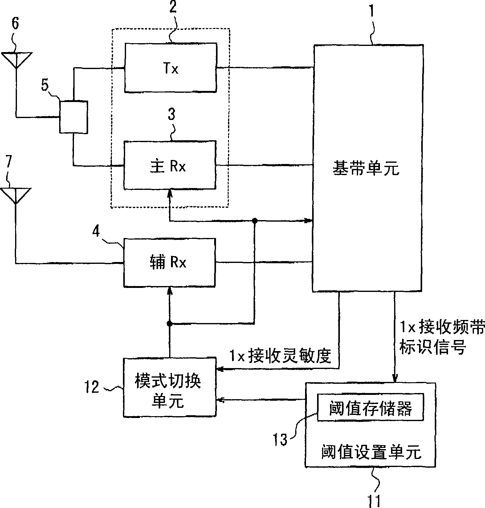
[0073] figure 1 is a functional block diagram showing a schematic configuration of a cellular phone terminal as a wireless communication device according to the first embodiment of the present invention. same Figure 8 Similarly, the cellular phone terminal according to the present embodiment includes: 1x first wireless communication system and 1xEVDO second wireless communication system in 800MGz band and 2GHz band, and is also equipped with 1.5GHz band GPS frequency reception function.

[0074] exist figure 1 , a transmission unit (Tx) 2, a main reception unit (main Rx) 3, and a secondary reception unit (secondary Rx) 4 are connected to a baseband unit 1 having a modulation circuit and a demodulation circuit. The transmitting unit 2 and the main receiving unit 3 are connected to the main antenna 6 through the duplexer 5, and are capable of transmission / reception at the 800 MHz band and the 2 GHz band. In addition, the sub receiving unit 4 is connected to the sub antenna ...

no. 2 example

[0088] Figure 5 is a functional block diagram showing a schematic configuration of a cellular phone terminal according to a second embodiment of the present invention.

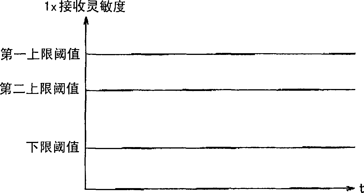
[0089] In this embodiment, in order to enable EVDO communication immediately after the cellular phone terminal is turned on, in a manner similar to that in the first embodiment, the threshold value (in this case, the first fixed value) set for each terminal is set in advance. (for 800MHz band) and second fixed value (for 2GHz band)) as the first upper threshold (for 800MHz band) and second upper threshold (for 2GHz band) to switch from hybrid mode to SHDR mode . Nevertheless, subsequently, based on the actual receiving sensitivity of the main receiving unit 3 and the auxiliary receiving unit 4 for EVDO communication diversity reception, the distance between the transmitting / receiving unit including the main antenna 6 and the receiving unit including the auxiliary antenna 7 was measured. Gain difference, and...

no. 3 example

[0101] In the third embodiment of the present invention, in such as Figure 5 In the illustrated cellular phone terminal, based on the gain difference between the transmitting / receiving unit including the main antenna 6 and the receiving unit including the auxiliary antenna 7 measured by the gain difference measuring unit 15 of the threshold setting unit 11, in Threshold calculation unit 17 calculates an upper limit threshold in the EVDO communication band and an upper limit threshold in another communication band, and sets a first upper limit threshold and a second upper limit threshold, respectively.

[0102] In other words, when the gain difference between the main antenna 6 and the auxiliary antenna 7 in the EVDO communication frequency band (e.g., 800 MHz frequency band) changes with the way the user holds the cellular phone terminal or changes in the surrounding environment, another communication channel (e.g., , 2GHz frequency band) the gain difference between the main ...


PUM


Abstract

A wireless communication method and a wireless communication apparatus capable of efficiently improving communication throughput of a second wireless communication system while securing a capturing capability of informative information in a first wireless communication system are provided. A transmitting/receiving unit (2, 3, 6) capable of transmitting/receiving information through first and second wireless communication systems (1x and EVDO) and a receiving unit (4, 7) capable of receiving information through the first and second wireless communication systems and whose reception gain in the first wireless communication system is smaller than the transmitting/receiving unit are used to detect that a reception sensitivity of informative information notifying a reception by the transmitting/receiving unit through the first wireless communication system has exceeded a first threshold or a second threshold set in accordance with a reception gain difference between the transmitting/receiving unit and the receiving unit when information is being transmitted/received by the transmitting/receiving unit through the second wireless communication system, and to switch reception of the informative information from the transmitting/receiving unit to the receiving unit.

Description

[0001] Cross References to Related Applications [0002] This application is based on and claims the benefit of priority from Japanese Patent Application No. 2006-264790 filed on September 28, 2006, the entire contents of which are hereby incorporated by reference. technical field [0003] The invention relates to a wireless communication method and a wireless communication device for realizing the method. Background technique [0004] In recent years, for wireless communication devices such as cellular phones, there are various systems conforming to various standards. For example, in Japan, as a cellular phone system, a TDMA system and a CDMA system have been popularized. [0005] Typically, wireless communication devices are configured to accommodate either standard. Nevertheless, recent cellular phone systems reflect a shift to multi-band since there is a limitation on frequency bands allocated to corresponding systems due to the increase in terminals. In addition, in ...

Claims


Application Information

Patent Timeline
Patent Type & Authority Applications(China)
IPC IPC(8): H04W68/12H04W88/06
CPCH04W88/06H04W68/12
Inventor 井上裕司
Owner KYOCERA CORP
Why Eureka
Try Eureka