Warship-targeted radar scattering cross section detecting method

A technology of radar scattering cross section and detection method, which is applied to radio wave measurement systems, instruments, etc., and can solve problems such as inapplicability

Inactive Publication Date: 2009-09-09
TSINGHUA UNIV
View PDF0 Cites 14 Cited by
  • Summary
  • Abstract
  • Description
  • Claims
  • Application Information

AI Technical Summary

Problems solved by technology

When the target is a plane, the calculation result of this met

Method used


Image

  • Warship-targeted radar scattering cross section detecting method
  • Warship-targeted radar scattering cross section detecting method
  • Warship-targeted radar scattering cross section detecting method

Examples


Embodiment Construction

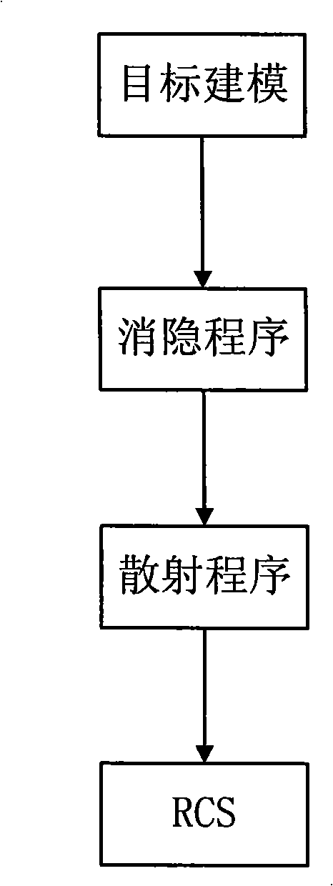
[0082] Take ships as an example. We use commercial software and the present invention to calculate the radar cross section of the ship respectively. The calculation steps of the present invention are as follows:

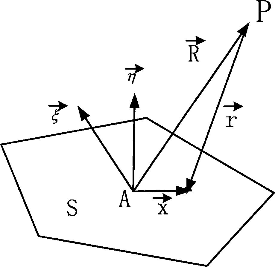
[0083] a) Set the coordinate axes, the direction perpendicular to the side of the ship on the horizontal plane is the Z axis, the direction perpendicular to the Z axis on the horizontal plane is the X axis, and the direction perpendicular to the horizontal plane is the Y axis.

[0084] b) To model the target, use N polygons to express the surface of the target. The size of N varies according to the surface complexity of the target and the accuracy of the results. The polygons can be arbitrary, and each polygon is composed of a A group of three-dimensional point sets in counterclockwise order. Input the N polygons into the Matlab array in any order, and draw a stereoscopic perspective, such as Figure 4 shown.

[0085] c) Rotate the model counterclockwise along th...


PUM


Abstract

The invention provides a warship-targeted radar scattering cross section detecting method, belonging to the field where the radar scattering cross section (RCS) of a target object is analyzed in high speed by using graphic electromagnetic computing (GRECO) technology. The detecting method is characterized in that a model expressed by a polygon is made for the target object. And a physical optical scattering equation is used to be combined with the blanking technology of computer graphics to improve the calculation of RCS. The subdivision is no longer required for the object. Therefore, the calculation cost has no relation with frequency. The introduction of blanking also solves defects in precision during the calculation, thus the high frequency radar scattering cross section can be calculated precisely in high speed.

Description

technical field [0001] The invention belongs to the field of analyzing the radar cross-section (RCS) of a target object at a high speed by using the graph electromagnetic computing (GRECO) technology. Background technique [0002] Graphical Electromagnetic Computing (GRECO) technology is considered to be the most effective method in the field of electromagnetic scattering theory to analyze the radar cross section RCS of complex targets. At present, the more common graphics calculation methods are the subdivision calculation method of commercial software and the method realized by using Open GL, the standard interface technology of graphics software. [0003] 1. Subdivision algorithm of commercial graphics computing software: [0004] This method is limited by the calculation speed and storage space. The subdivision must decompose the target into small triangles with a scale no larger than 1 / 3 of the wavelength for calculation. The number of planar units after subdivision is...

Claims


Application Information

Patent Timeline
IPC IPC(8): G01S7/41
Inventor 贾洪涛张志军陈文华冯正和
Owner TSINGHUA UNIV
Why Eureka
Try Eureka