
Fire detection system and method thereof

A fire detection and fire technology, applied in the field of fire detection systems, can solve the problems of inability to adjust the focal length to obtain the image of the protection area, manually adjust the focal length, and reduce the sensitivity, so as to improve the ability to prevent false alarms and missed alarms, and the system is reliable. Effect

Active Publication Date: 2009-09-09
丁国锋
View PDF0 Cites 28 Cited by
  • Summary
  • Abstract
  • Description
  • Claims
  • Application Information

AI Technical Summary

Problems solved by technology

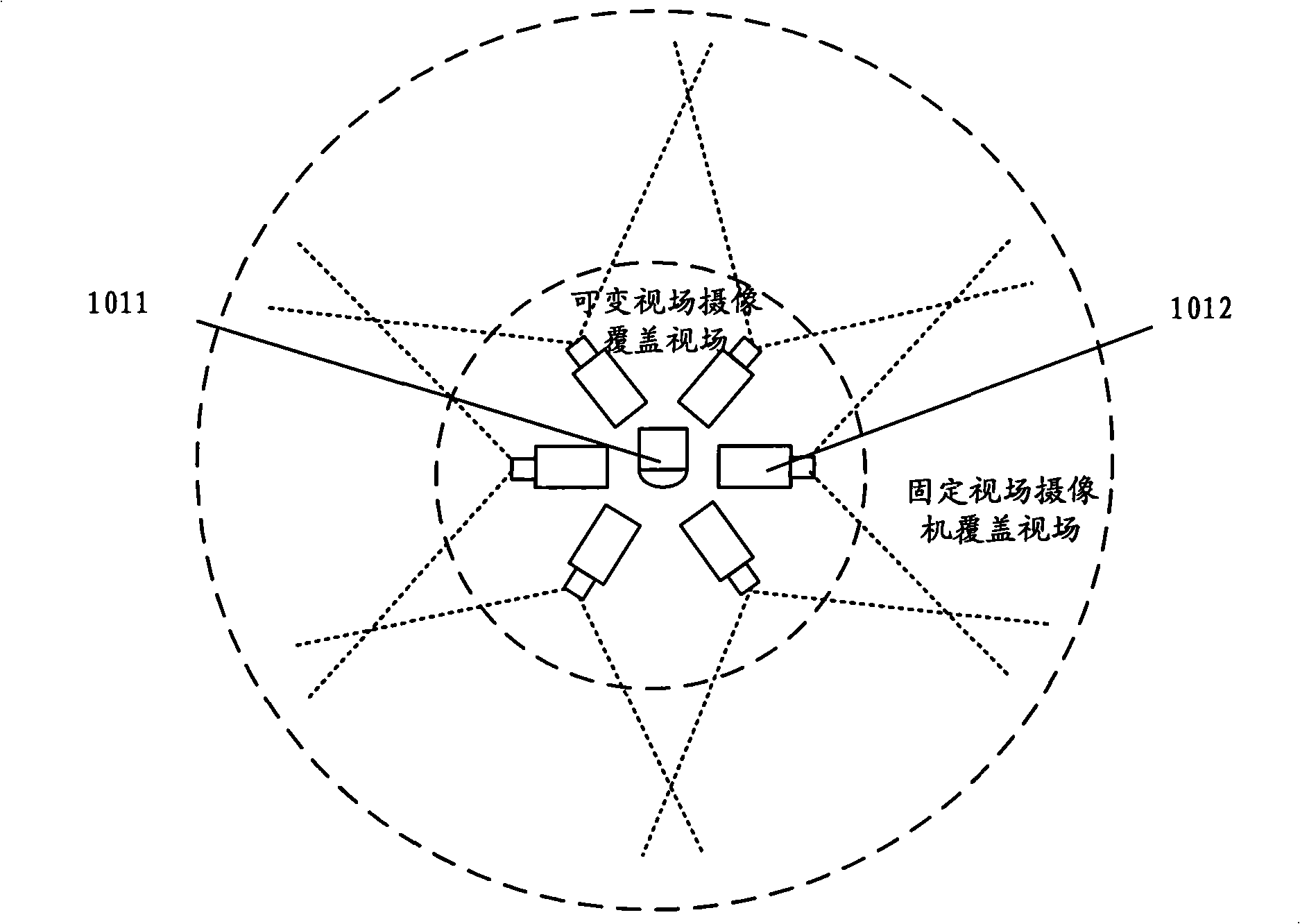
[0004] However, there are also some problems in the image-based fire detection system. For example, the coverage field of view of the system is limited by the performance of the camera, and the sensitivity is limited by the detection distance. For example, for a CCD (Charge Coupled Device, charge-coupled device) and a fixed field of view camera with a focal length of 8mm, its horizontal coverage field of view angle is only 32 degrees, that is to say, several sets of fixed fields of view are often required to completely protect a certain protection area camera system; in addition, since the imaging size of an object of the same size on the CCD is inversely proportional to the distance, the visible features of the fire in the acquired near image are obvious, and the visible features of the fire in the acquired distant image may be It cannot be identified, the detection distance of the system is limited, and the sensitivity decreases with the increase of distance
[0005] Of course, there is also a system that uses a pan-tilt to drive the camera to rotate 360 ​​degrees to detect fires in a large space. This system can theoretically cover a large field of view. The image of the protection area, or the focus can only be adjusted manually, and the focus cannot be automatically adjusted according to the requirements to obtain the image of the protection area

Method used


Image

  • Fire detection system and method thereof
  • Fire detection system and method thereof
  • Fire detection system and method thereof

Examples


Embodiment Construction

[0069] The specific implementation manners of the present invention will be further described in detail below in conjunction with the accompanying drawings and embodiments.

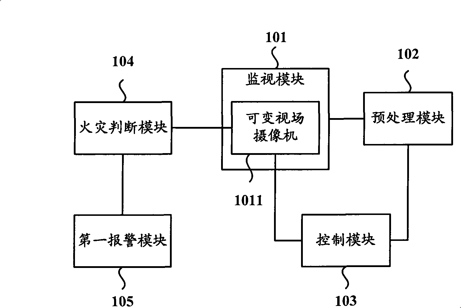
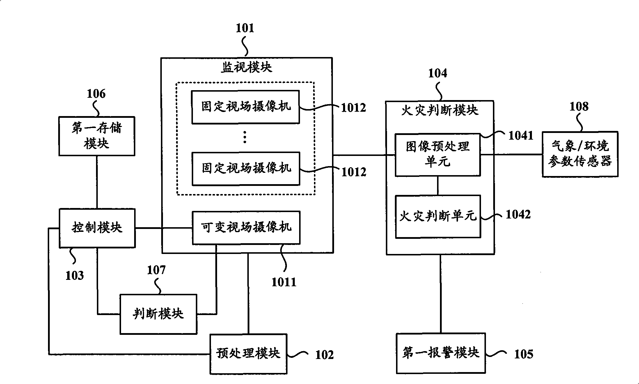
[0070] Such as figure 1 Shown is a schematic structural diagram of a fire detection system according to an embodiment of the present invention, and the fire detection system includes:

[0071] A monitoring module 101, configured to obtain fire monitoring information of a preset protection area, the preset protection area is within the monitoring range of the monitoring module 101, and the monitoring module 101 includes a variable field of view camera 1011;

[0072] The so-called variable field of view camera is a camera that can adjust the shooting angle and shooting focal length, corresponding to the fixed field of view camera, which can only acquire images at a fixed angle and fixed focal length;

[0073] A preprocessing module 102, connected to the monitoring module 101, is used to analyze and process...


PUM


Abstract

The invention provides a fire detection system and a method thereof. The system comprises a monitoring module which is used for obtaining fire monitoring information of a preset protection area and also comprises a variable-viewing field vidicon, a pretreating module which is connected with the monitoring module and is used for analyzing and processing the fire monitoring information and obtaining a suspected fire occurring area of the preset protection area, a control module which is connected with the pretreating module and the variable-viewing field vidicon and is used for controlling a close-shot image of the suspected fire occurring area obtained by the variable-viewing field vidicon, a fire judgement module which is connected with the variable-viewing field vidicon and is used for judging whether fire occurs in the preset protection area according to the close-shot image of the suspected fire occurring area and obtaining a judgement result and a first warning module which is connected with the fire judgement module and is used for outputting warning information when the judgement result shows that fire occurs in the preset protection area. The fire detection system can obtain the close-shot image of the fire occurring area automatically.

Description

technical field [0001] The invention relates to fire safety monitoring technology, in particular to a fire detection system and method. Background technique [0002] In recent years, with the continuous development of social economy and civilization, the trend of global warming has also accelerated. The main cause of global warming is due to CO 2 A large number of emissions such as gases, according to statistics, 20% of CO per year 2 of gas emissions are due to fires, especially in large spaces such as forests and warehouses. The early detection of large-scale space fires is difficult to deal with effectively. In the prior art, there is a satellite-based fire detection system for detecting large-scale space fires. However, this system can only be detected when the fire develops to a certain scale. [0003] At present, image-based fire detection systems are gradually being applied to early fire detection in large spaces. The image-based fire detection system does not depen...

Claims


Application Information

Patent Timeline
IPC IPC(8): G08B17/00H04N7/18
Inventor 丁国锋
Owner 丁国锋
Learn More