Visualized phase-array fire alarm system

A fire alarm system and a technology for an alarm system, applied in the field of fire alarm systems, can solve the problems of high cost of multi-lens array focusing and lens occlusion, lack of visible light image level and three-dimensional sense, inconvenient alarm parameters and intuitive observation, etc. Wide range of applications, convenient for large-scale promotion and use, and saving installation and debugging time

Active Publication Date: 2013-01-02
江苏弘冉智能科技有限公司
View PDF6 Cites 46 Cited by
  • Summary
  • Abstract
  • Description
  • Claims
  • Application Information

AI Technical Summary

Problems solved by technology

Although infrared thermal imaging fire detection technology is intuitive and reliable, its high-resolution thermal imaging chip lacks the level and three-dimensionality of visible light images due to the very weak thermal image distribution signal of the infrared radiation of each part of the target object, so some research is required. Image brightness and contrast control, actual correction and false color rendering, etc., the processed signal is sent to the video signal forming part for data conversion and forms a standard thermal imaging video signal, and finally displays the measured target through the TV screen or monitor Infrared thermal imaging, its complex technology leads to high cost, especially the thermal imaging chip has higher requirements on the working environment temperature. In higher temperature places, in order to ensure the detection accuracy, it is often necessary to install cooling devices such as water circulation, such as "SAT-CK350 -W Infrared thermal imaging monitoring system" is a water-cooled thermal imaging camera adapted to monitor in harsh envi

Method used


Image

  • Visualized phase-array fire alarm system
  • Visualized phase-array fire alarm system
  • Visualized phase-array fire alarm system

Examples


Embodiment Construction

[0023] Two typical embodiments of the present invention will be further explained below in conjunction with specific drawings.

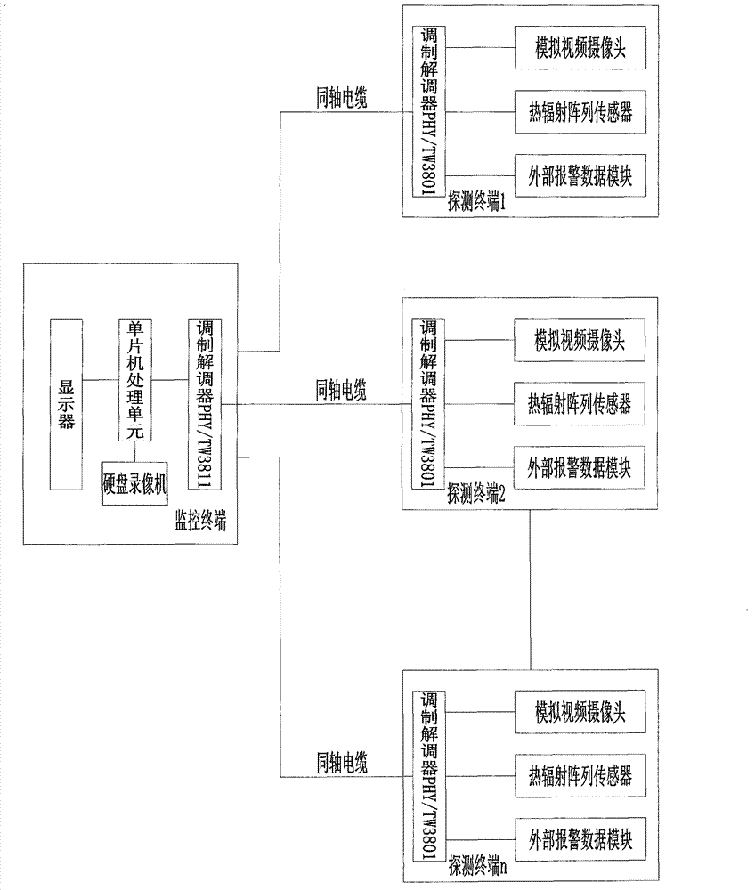
[0024] Embodiment (one) is a kind of visual phase array fire alarm system based on coaxial cable signal transmission line and analog video camera, including N groups (determining the specific number according to the requirements of the scene) detection terminals and monitoring terminals, such as figure 1 As shown, each group of detection terminals includes a thermal radiation array sensor, a visible light camera, an external alarm data interface module, and a signal composite processing and transmission module. The monitoring terminal is composed of a signal transmission module, a hard disk video recorder, a single-chip microcomputer, and a display. The cable signal transmission line is connected to the monitoring terminal.

[0025] The visible light camera described in embodiment (1) is an analog camera with a viewing angle of 60°.

[0026]The ther...


PUM


Abstract

The invention discloses a visualized phase-array fire alarm system which comprises a detection terminal and a monitoring terminal, wherein the detection terminal comprises a thermal radiation array sensor, a visible light camera, an external alarm data interface module and a signal composite processing transmission module, the monitoring terminal is composed of a data storage processor and a display or a computer with a display screen, and the detection terminal is connected to the monitoring terminal through a signal wire. The invention provides a visualized phase-array fire alarm system which is based on a complicated environment, regionally detects and displays temperature changes, regionally sets up alarm parameters, is compatible with various fire detection signal data and low in cost, and has a self-learning function; and according to the invention, the early property, visualization, intelligentization and systematization of fire alarming are realized, and the false alarm rate and cost of the system can be greatly reduced, thereby reducing the fire loss.

Description

technical field [0001] The invention relates to a fire alarm system, in particular to a visual phase array fire alarm system, which is used for early fire pre-alarm and fire alarm in complex environment spaces. Background technique [0002] At present, the detection technologies used in commonly used fire alarm systems mainly include smoke detection, carbon monoxide detection, flame detection, and temperature detection. It starts from the temperature rise, and simultaneously or gradually generates smoke or open flames, and no matter what kind of fire process, temperature rise is a necessary factor for fire, so the general detection technology can only issue an alarm after the fire occurs, and the false alarm rate is high Less reliable. Regardless of the type of combustion, such as flash ignition, ignition, spontaneous combustion, explosion, etc., one of the necessary conditions for its initiation is related to the appropriate temperature. The increase in the temperature of ...

Claims


Application Information

Patent Timeline
IPC IPC(8): G08B17/00G08B25/00
Inventor 朱清
Owner 江苏弘冉智能科技有限公司
Why Eureka
Try Eureka