Method for measuring thickness of coating in confocal mode

A layer thickness, confocal technology, applied in the detection field, can solve problems such as changes, edge bulges, and cone wear, and achieve the effect of improving measurement accuracy and work efficiency

Inactive Publication Date: 2013-12-18
ANGANG STEEL CO LTD
View PDF5 Cites 23 Cited by
  • Summary
  • Abstract
  • Description
  • Claims
  • Application Information

AI Technical Summary

Problems solved by technology

Ordinary optical microscopes can only measure the distance between two points of the coating in the drilled hole, and the edge of the drilled hole will often be raised due to mechanical stress and other reasons, and there are objections to the measurement accuracy. It is inevitable that there will be wear and tear, which will change the actual taper more or less and affect the accuracy of the results

Method used


Image

  • Method for measuring thickness of coating in confocal mode
  • Method for measuring thickness of coating in confocal mode
  • Method for measuring thickness of coating in confocal mode

Examples


Embodiment 1

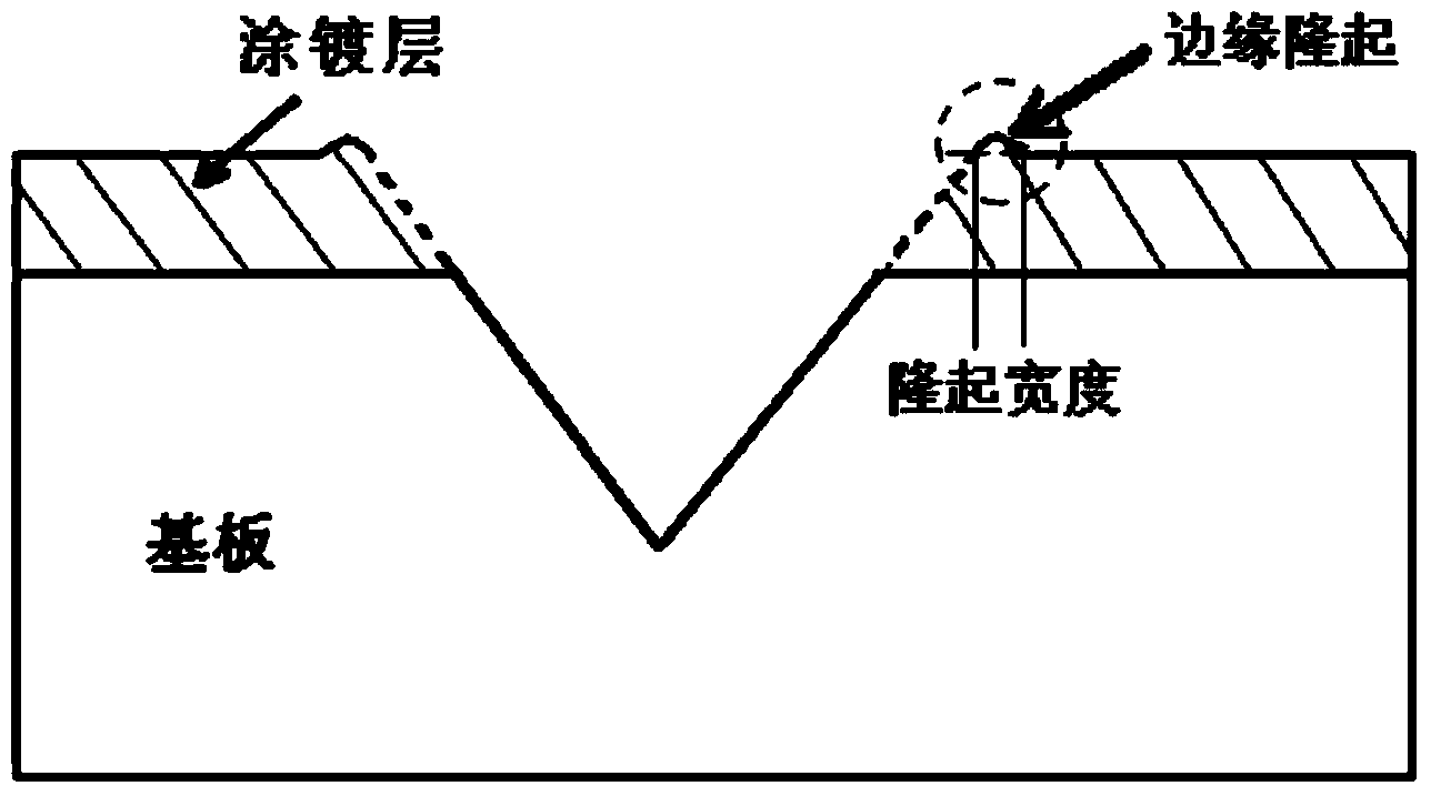
[0039] The color-coated steel plate is used, and the thickness of the color-coated topcoat is measured by combining V-shaped drilling and laser confocal technology.

[0040] 1) Use a conical head with a taper of 30° to drill a V-shaped hole on the surface of the color-coated steel plate with a depth of 0.15mm. See figure 1

[0041] 2) Focus on the V-shaped hole area in the visible light mode of the laser confocal microscope, and enter the laser mode after it is clear.

[0042] 3) Scan layer by layer in laser mode to obtain the two-dimensional shape of the V-shaped hole.

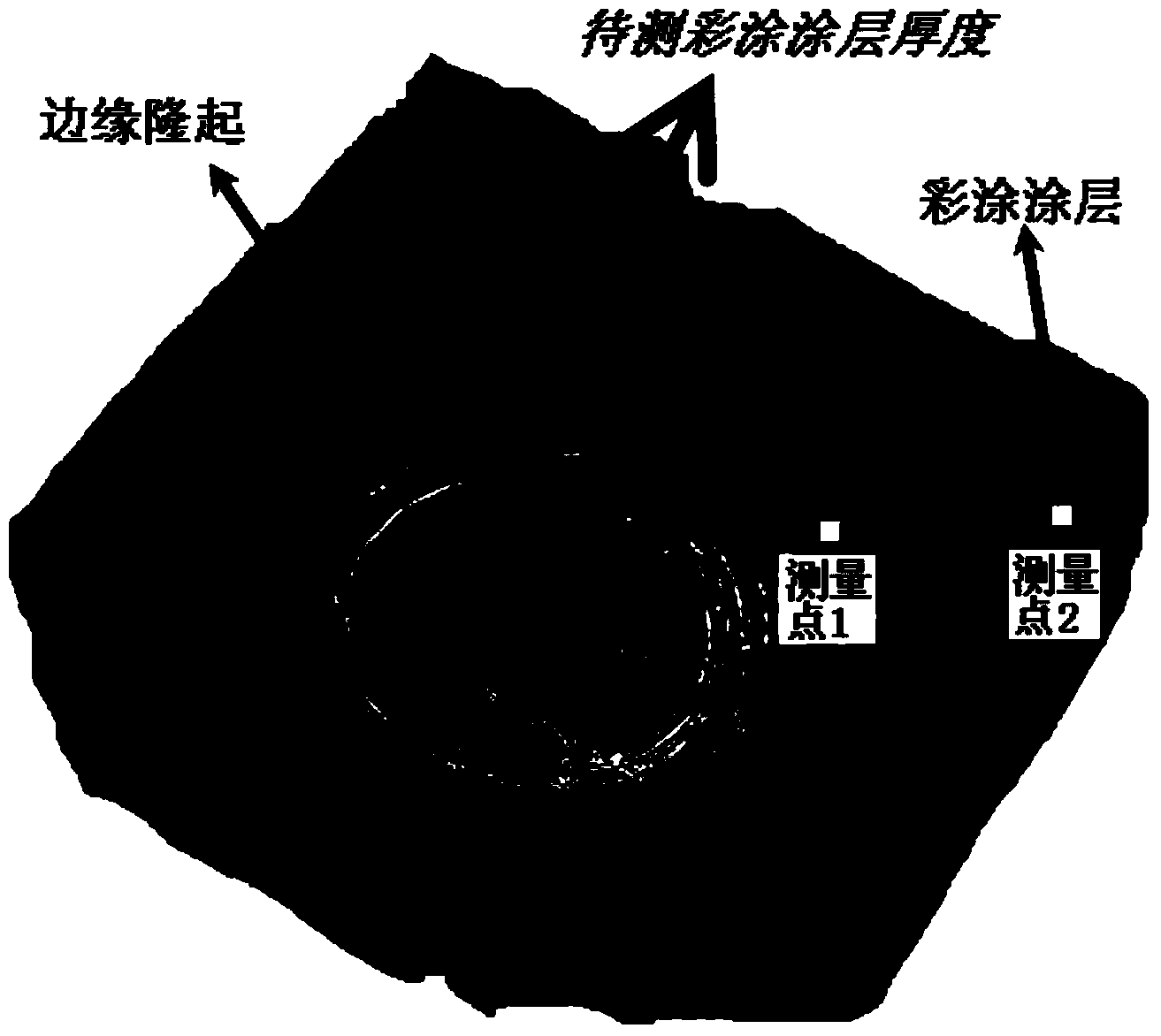
[0043] 4) Perform noise and filter processing on the two-dimensional topography map, and switch to three-dimensional topography, such as figure 2 shown.

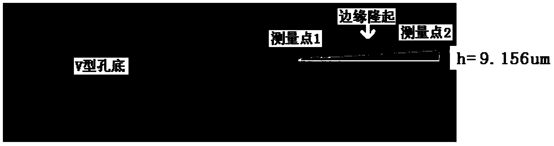
[0044] 5) Select figure 2 The measurement point 1 of the junction between the medium color coating and the substrate and the measurement point 2 that is 2.5 times away from the edge of the V-shaped hole, read the height difference between point 1 an...

Embodiment 2

[0046] Using hot-dip galvanized steel plate, the thickness of galvanized layer is measured by combining V-shaped drilling and laser confocal technology.

[0047] 1) Use a conical head with a taper of 20° to drill a V-shaped hole on the surface of the color-coated steel plate, and the hole depth is about 0.15mm.

[0048] 2) Use 0.5vol% nital to etch the V-shaped hole area so that the zinc layer and the substrate can be distinguished in confocal mode.

[0049] 2) Focus on the V-shaped hole area in the visible light mode of the laser confocal microscope, and enter the laser mode after it is clear.

[0050] 3) Scan layer by layer in laser mode to obtain the two-dimensional shape of the V-shaped hole.

[0051] 4) Perform noise and filter processing on the two-dimensional topography map, switch to three-dimensional topography, Figure 4 The three-dimensional topography diagram of the V-shaped hole area of ​​the galvanized layer is given, Figure 4 The alloy layer between the galv...

Embodiment 3

[0054] The color-coated steel plate is used, and the thickness of the color-coated primer is measured by combining V-shaped drilling and laser confocal technology.

[0055] 1) Use a conical head with a taper of 60° to drill a V-shaped hole on the surface of the color-coated steel plate with a depth of 0.15mm.

[0056] 2) Focus on the V-shaped hole area in the visible light mode of the laser confocal microscope, and enter the laser mode after it is clear.

[0057] 3) Scan layer by layer in laser mode to obtain the two-dimensional shape of the V-shaped hole.

[0058] 4) Perform noise and filter processing on the two-dimensional topography map, switch to three-dimensional topography, and obtain the three-dimensional topography map of the V-shaped hole.

[0059] 5) Directly select the measurement point of the junction of the color-coated topcoat and the primer and the measurement point of the junction of the primer and the substrate to measure the height difference, so as to obta...


PUM


Abstract

The invention provides a method for measuring the thickness of a coating in a confocal mode. The method includes the steps of drilling a small conical hole in the surface of the coating mechanically, carrying out imaging processing on the V-shaped-section hole in the laser scanning confocal microscope three-dimensional imaging technique, measuring the height difference between the junction of the coating in the V-shaped hole and a substrate and the outer surface of the coating with the confocal height difference measurement function, and then determining the thickness of color-coated coating finishing coat, the thickness of a hot-dipped coating and the thickness of color-coated coating undercoat respectively. According to the method, the factors of conicity and the like do not need to be considered, the thickness of the coating can be truly reflected, measurement accuracy can be greatly improved, the thickness of a coating in a micro area can be measured, and coating uniformity can be examined. By being changed slightly according to the characteristics of coatings and substrates, the method can be applied to thickness measurement of various types of coatings such as galvanized coatings, PVD plating and CVD plating.

Description

Technical field [0001] The present invention is the field of detection technology, especially involving a method of mechanical drilling and combining the thickness of the coating layer. Background technique [0002] The coating layer has been widely used in various products. Due to its special performance, the coating layer can play a great role in various fields, such as enhancing the surface aesthetics of the product;Referring, superconductivity, etc.); and improving the product's corrosion resistance, abrasion resistance, etc. [0003] The control of the coating layer's thickness to a large extent affects the use of materials, especially in the aspect of corrosion resistance and abrasion resistance directly affects the service life of the material.The coating layer thickness obtained under various process parameters needs to be measured by a certain detection method to determine whether the layer thickness under the process control meets the requirements. Therefore, the accura...

Claims


Application Information

Patent Timeline
Patent Type & Authority Applications(China)
IPC IPC(8): G01B11/06G01N21/84
Inventor 杨洪刚李锋吕家舜周芳徐承明王永明
Owner ANGANG STEEL CO LTD
Why Eureka
Try Eureka